Modular Rotor For Synchronous Reluctance Machine

a synchronous reluctance machine and rotor technology, applied in the direction of dynamo-electric machines, magnetic circuit rotating parts, magnetic circuit shape/form/construction, etc., can solve the problem of limiting the size or robustness of synchronous reluctance machines, limitations may be important, and prior art rotor designs are not optimum for enabling simple manufacturing techniques, etc. problem, to achieve the effect of increasing the power factor of the machine, facilitating simple manufacturing, and facilitating the problem o

Inactive Publication Date: 2012-06-14
ABB RES LTD
View PDF9 Cites 13 Cited by
  • Summary
  • Abstract
  • Description
  • Claims
  • Application Information

AI Technical Summary

Benefits of technology

[0008]It is in particular an object of the invention to provide such a rotor, which is mechanically strong and robust while still high electric performance is maintained. Simultaneously, the manufacturing method should be simple and flexible.
[0027]In one embodiment the plurality of rotor modules is bonded to one another. By such provision, the rotor structure is further strengthened and the rotor does eventually not need any rotor shaft traversing through the rotor modules.

Problems solved by technology

For both rotor structures described above mechanical weakness may limit the size or robustness of the synchronous reluctance machine.
In particular, for large synchronous reluctance machines in the megawatt region the above limitations may be important.
Further, the designs of the prior art rotors are not optimum for enabling simple manufacturing techniques to be used.

Method used


Image

  • Modular Rotor For Synchronous Reluctance Machine
  • Modular Rotor For Synchronous Reluctance Machine
  • Modular Rotor For Synchronous Reluctance Machine

Examples


Embodiment Construction

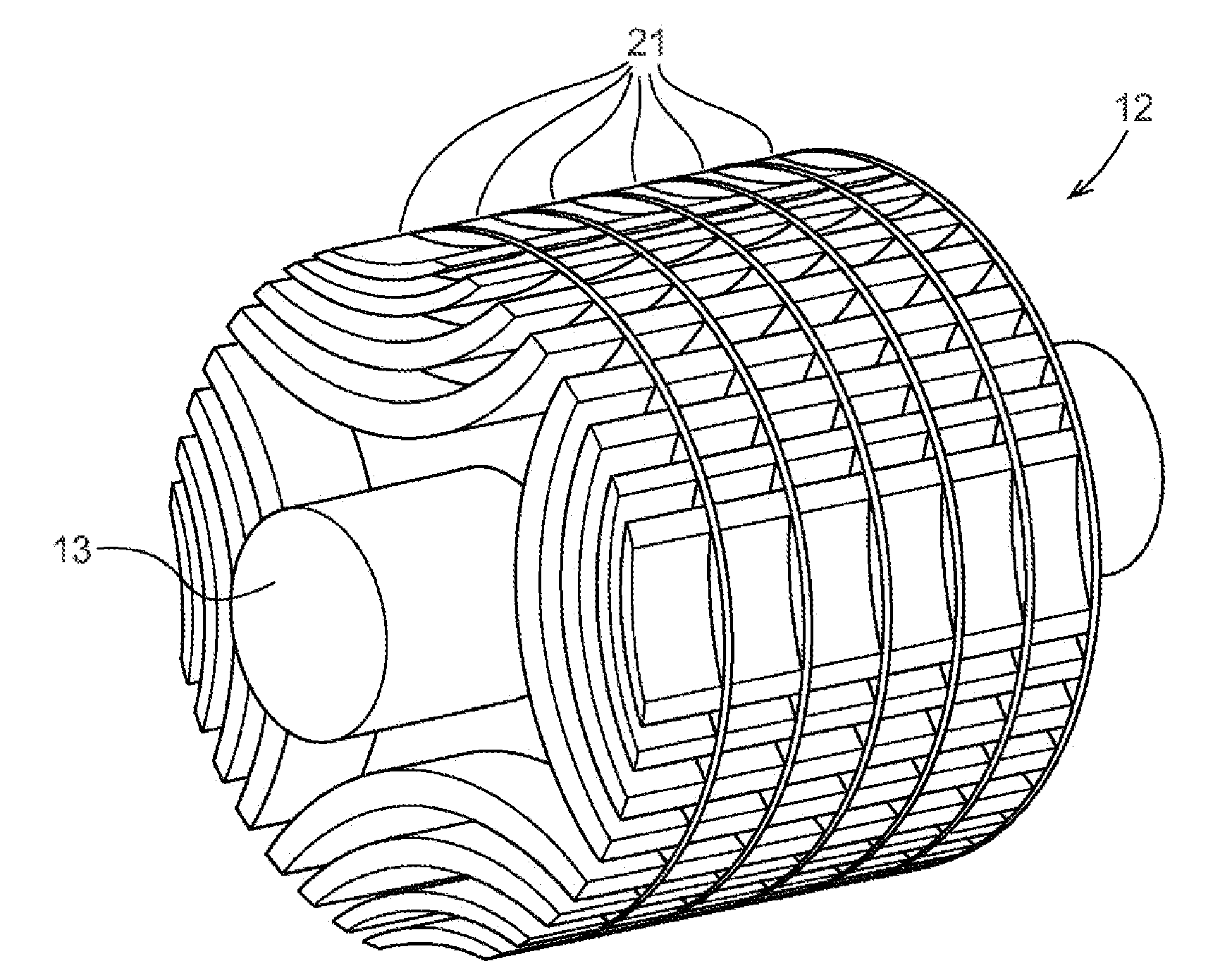
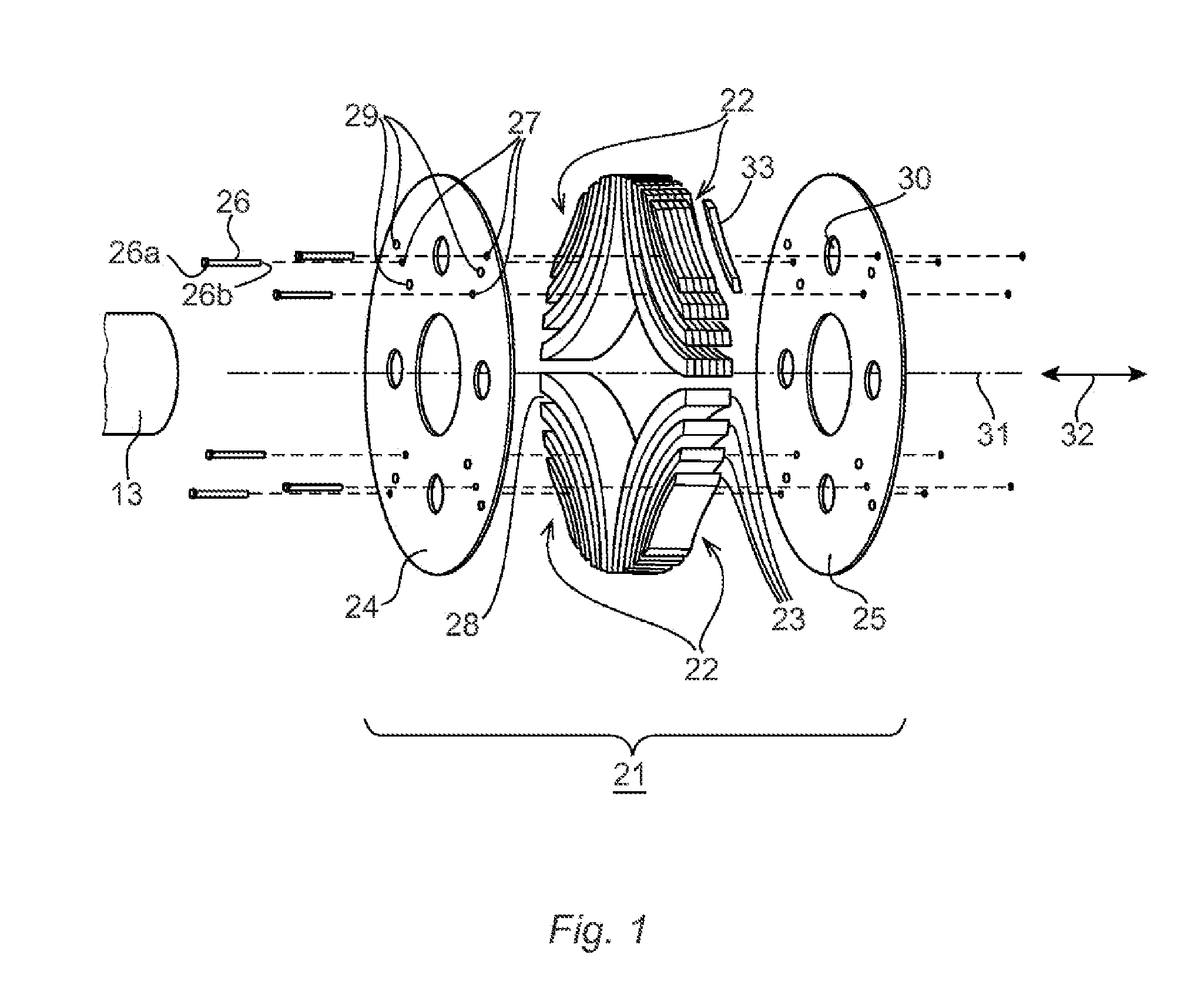
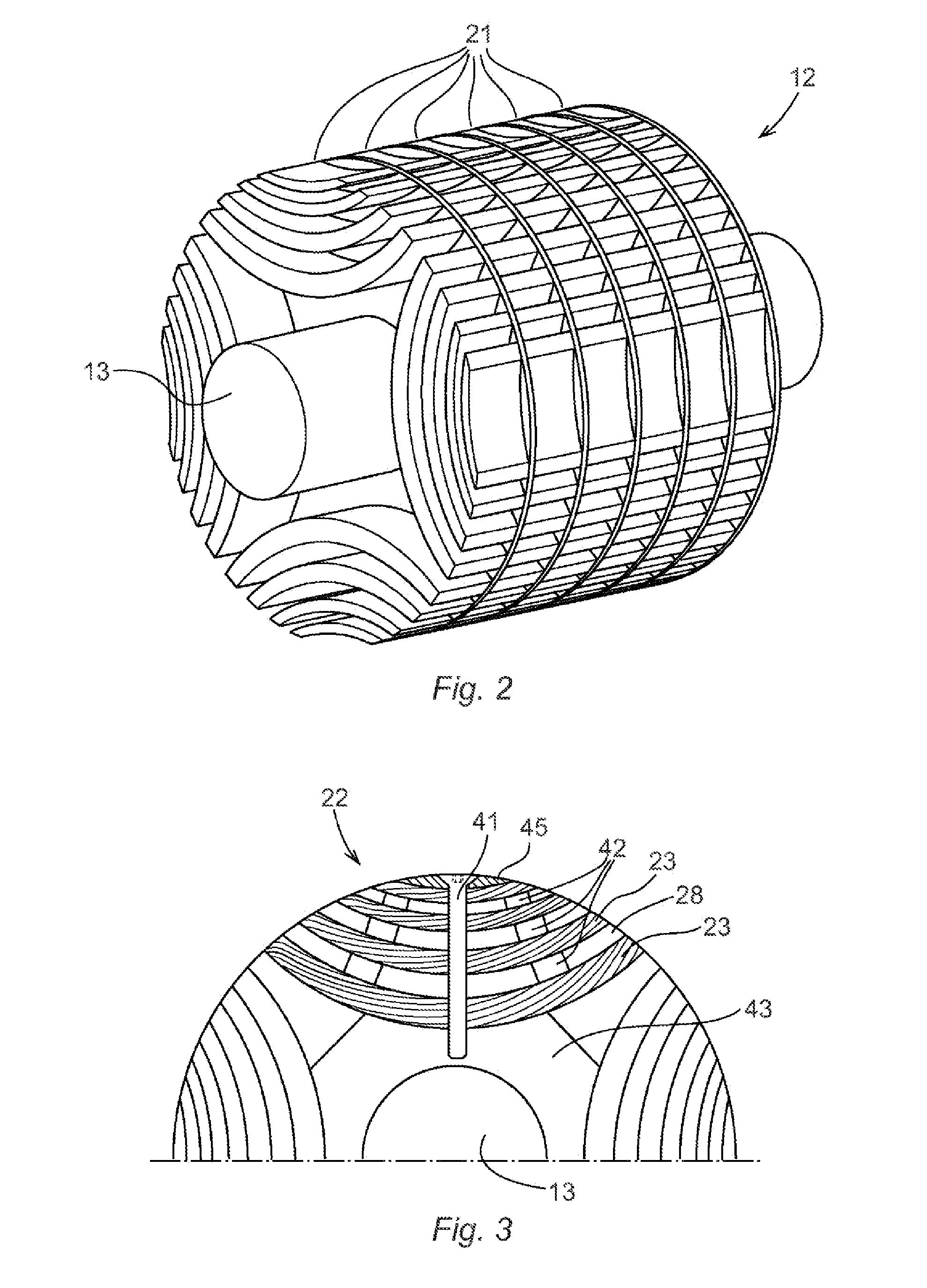
[0035]The rotor 12 is, in accordance with the present invention, formed by a plurality of rotor modules 21, of which one is schematically displayed in an exploded view in FIG. 1. The rotor modules 21 comprise a plurality of poles 22 disposed in adjacent sectors about a common axis 31, each pole 22 comprising a plurality of magnetic segments 23 spaced apart from one another in radial direction. The magnetic segments 23 preferably comprise a plurality of laminates 33 stacked in an axial 32 or radial direction.

[0036]The rotor modules 21 further comprise a support plate 24, 25 to which the plurality of poles 22 is bonded. The bonding is implemented e.g. via adhesives, welding or fasteners. The same bonding means may be used to bond the laminates 33 to one another.

[0037]According to the embodiment of FIG. 1, two support plates 24, 25 preferably of a non-magnetic material are provided on axially opposite sides of the poles 22. The support plates 24, 25 may be of austenitic steel but are p...


PUM


Abstract

A rotor for a synchronous reluctance machine includes a plurality of rotor modules disposed in an axial sequence along a common axis. Each rotor module includes a plurality of poles disposed in adjacent sectors about the common axis, each pole including a plurality of magnetic segments spaced apart from one another in radial direction, a support plate, provided on an axial side of the plurality of poles, and fastening means for fastening the plurality of poles to the support plate. The fastening means, preferably a plurality of axially arranged bolts or an adhesive, bonds the plurality of poles to the support plate.

Description

CROSS-REFERENCE TO RELATED APPLICATIONS[0001]The present application is a continuation of pending International patent application PCT / EP2009 / 060553 filed on Aug. 14, 2009 which designates the United States and the content of which is incorporated herein by reference.FIELD OF THE INVENTION[0002]The present invention generally relates to rotors for synchronous reluctance machines.BACKGROUND OF THE INVENTION[0003]GB 2 378 323 discloses a rotor for a synchronous reluctance machine comprising magnetic core steel laminates with a shaft hole and a plurality of flux barrier groups formed centered around the shaft hole, non-magnetic securing elements passing through the end plates and the laminate stack through the flux barrier groups. Stacking detents may be formed on each laminate around the shaft hole or between the flux barrier groups.[0004]U.S. Pat. No. 7,489,062 discloses a synchronous reluctance machine that has a rotor with laminates stacked in axial direction to form boat shaped se...

Claims


Application Information

Patent Timeline
Patent Type & Authority Applications(United States)
IPC IPC(8): H02K1/30
CPCH02K1/246
Inventor MOGHADDAM, REZA RAJABILIU, YUJINGMONNAY, CEDRICTENCA, PIERLUIGI
Owner ABB RES LTD
Why Eureka
Try Eureka