Touch pen

a technology of touch pen and pen tip, which is applied in the field of touch pen, can solve the problems of reducing sensitivity, limiting the operation angle of the touch pen tip, and not being perfect, so as to reduce friction, increase the sensitivity of the touch pen, and improve the touch effect

Inactive Publication Date: 2012-06-14
KOONER TECH TAIWAN
View PDF6 Cites 17 Cited by
  • Summary
  • Abstract
  • Description
  • Claims
  • Application Information

AI Technical Summary

Benefits of technology

[0005]The present invention relates to a touch pen, which is configured with a flexible covering for enabling the contact area between the touch pen and a touch panel to be increased during a touch of the two, and thus increasing the sensitivity of the touch pen so as to achieve a good touch effect. Moreover, the touch pen further has a fabric covering arranged surrounding the periphery of the flexible covering, that is used for reducing the friction between the touch pen and the touch panel during a touch of the two so as to improve the operation smoothness of the touch pen.

Problems solved by technology

Nevertheless, the touch pens that are current available are not perfect.
For instance, the touch pen with rubber pen tip not only is restricted by its limited operation angle and orientation, but also can suffer by decreasing sensitivity and short lifespan directly resulting from the high friction coefficient of the rubber tip and the rubber hardening after being used for a period of time.
On the other hand, for the touch pen with foam pen tip, the sensitivity thereof will also decrease with time since the foam pen tip is easily worn out or deformed during usage, not to mention that its conductivity is inferior.

Method used


Image

  • Touch pen
  • Touch pen
  • Touch pen

Examples


first embodiment

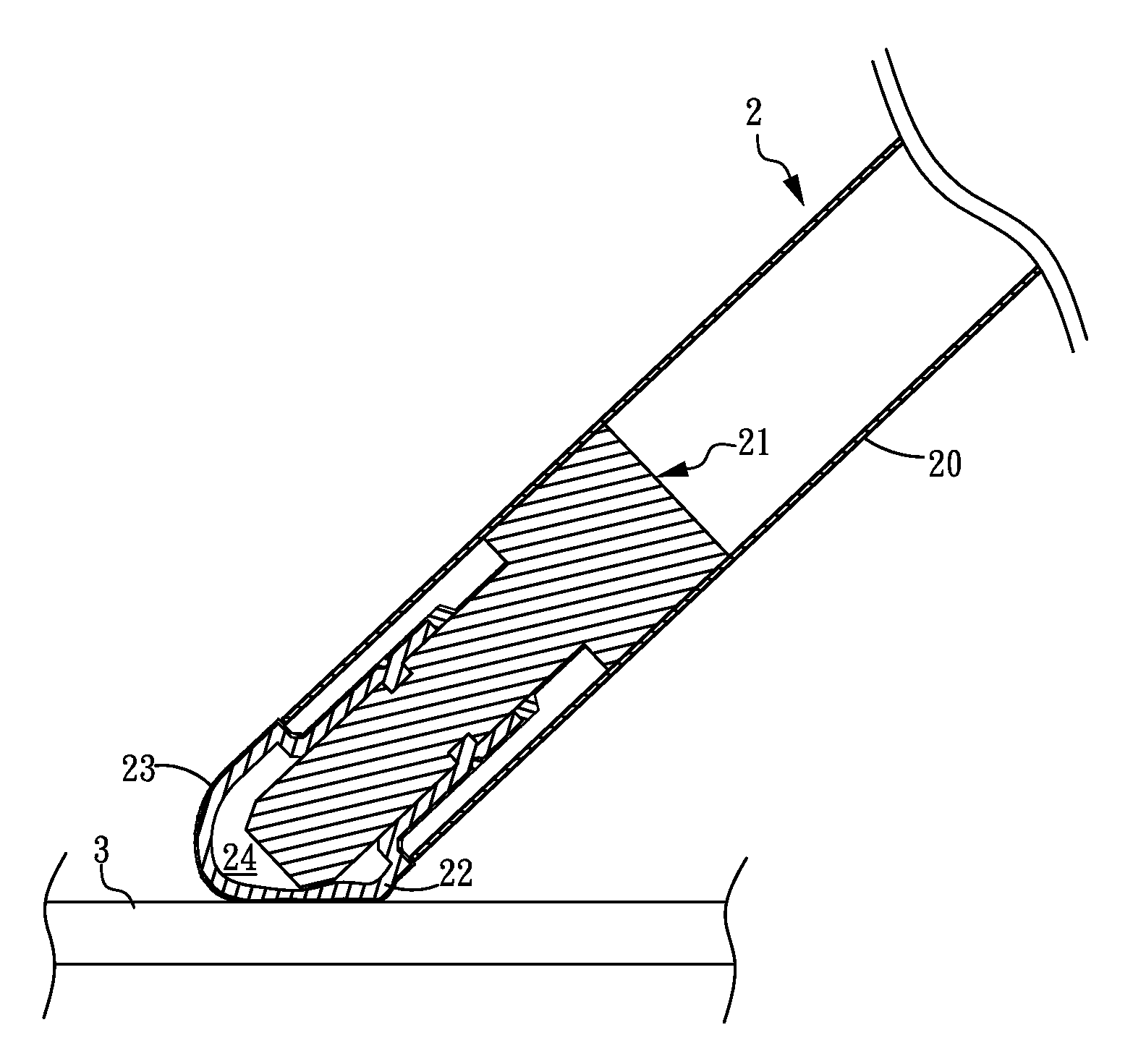
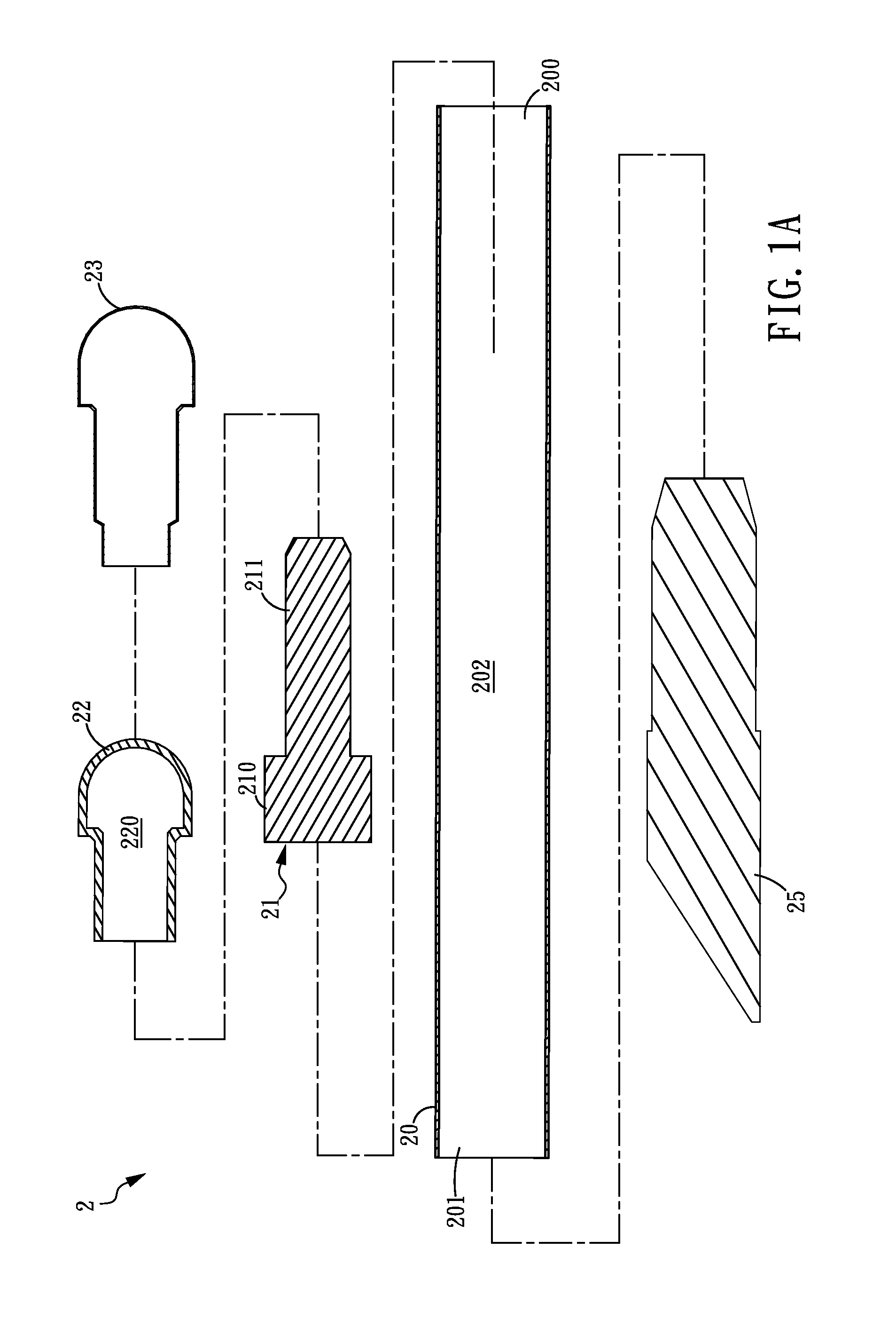
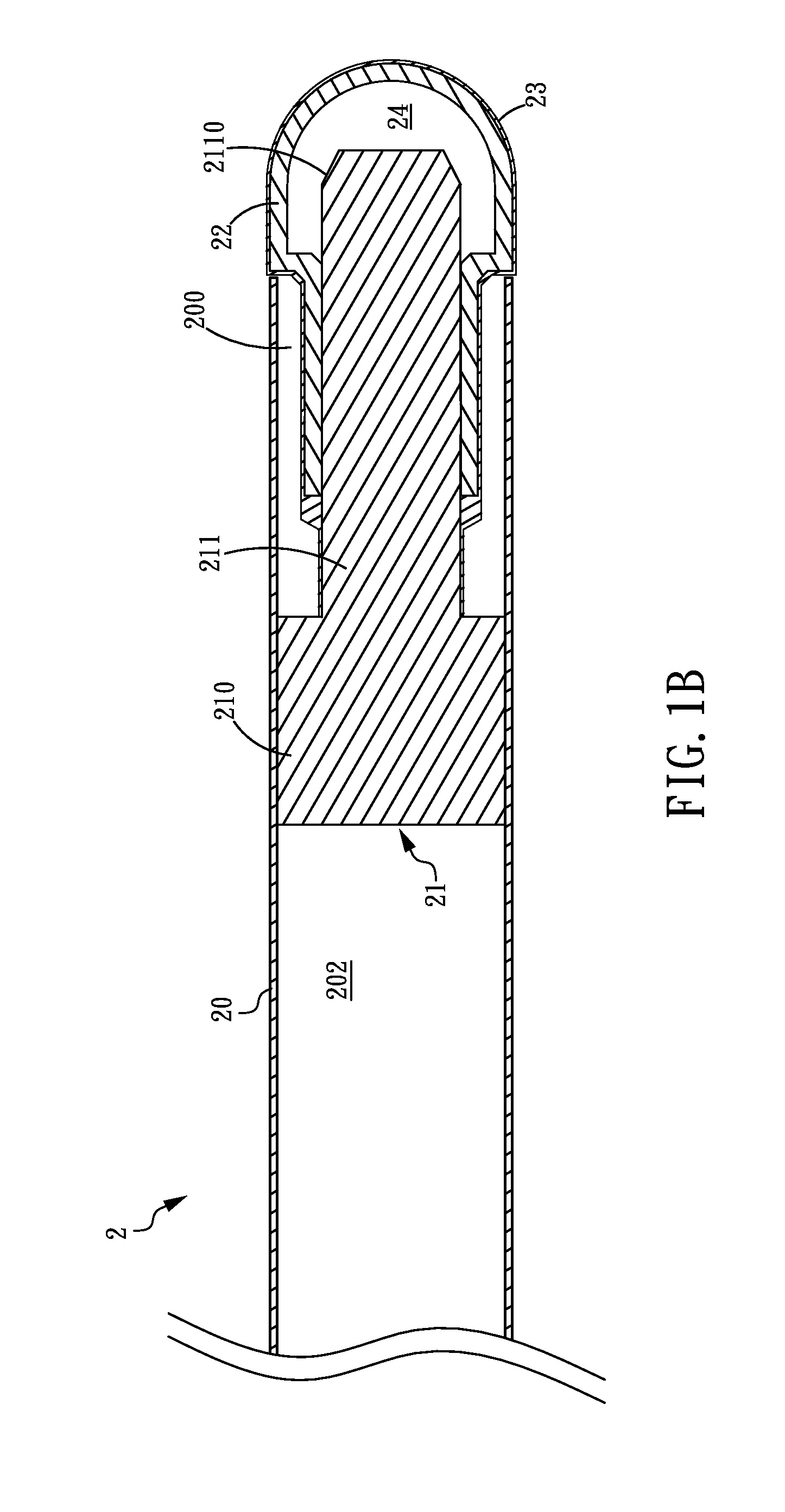
[0022]Please refer to FIG. 1A and FIG. 1B, which are an explode view and a cross sectional view of a touch pen according to the present invention. As shown in FIG. 1 and FIG. 2, the touch pen 2 is composed of: a penholder 20, a conducting core 21, a flexible covering 22 and a fabric covering 23, in which the penholder 20 is further configured with a first end 200 and a second end 201. In this embodiment, the penholder 20 is a hollow tube having an accommodation space 202 formed therein. However, in addition to the hollow tube-like structure, the penholder can be formed as a solid structure, as the penholder 20a shown in FIG. 2, which has two accommodation spaces 200a and 201a formed respectively at the two ends thereof. Moreover, the penholder 20 can be made of a metal, such as stainless steel, or a non-metallic material, such as plastic.

[0023]In the embodiment shown in FIG. 1A and FIG. 1B, the conducting core 21 is arranged coupling to the first end 200 of the penholder 20. In addi...

second embodiment

[0027]Please refer to FIG. 5A and FIG. 5B, which are an explode view and a cross sectional view of a touch pen according to the present invention. In this embodiment, the structure of the touch pen is basically the same as the one shown in FIG. 1A and FIG. 1B, but is different in that: there is a first ring-like groove 212 formed on the extension element 211 of the conducting core 21, and correspondingly, there is a first ring-like protrusion 221 formed on the flexible covering 22 at a position corresponding to the first ring-like groove 212. Thereby, while ensheathing the extension element 210 into the flexible covering 22, the first ring-like protrusion 221 will inset into the first ring-like groove 212 so that the fixing of the extension element 210 to the flexible covering 22 is strengthened. Similarly, there is a second ring-like groove 222 formed on the flexible covering 22, and correspondingly, there is a second ring-like protrusion 230 formed on the fabric covering 23 at a p...

third embodiment

[0028]Please refer to FIG. 6, which is an explode view of a touch pen according to the present invention. In this embodiment, the structure of the touch pen is basically the same as those shown in FIG. 1A and FIG. 5A, but is different in that: the touch pen further has a sleeve 27 to arranged ensheathing the conductive fabric covering 23, whereas the sleeve 27 is made of a material of low friction resistance. Moreover, in this embodiment, the sleeve 27 is substantially a non-conductive fabric sleeve. By the arranging of the non-conductive fabric sleeve that is shown in FIG. 6, the touch panels whose operation surfaces are protected by the use of a protective film with comparatively insufficient hardness can be prevented from being scratched by the conductive fabric covering 23. Moreover, since the e sleeve 27 is made of a material of low friction resistance, the friction between the touch pen and the touch penal can be reduced.

[0029]Please refer to FIG. 7, which is a schematic diagr...


PUM


Abstract

A touch pen comprises a penholder, an electrically conducting core, a flexible covering and fabric covering. The electrically conducting core is coupled to the penholder. The electrically conducting core is ensheathed in the flexible covering, while the fabric covering wraps around the flexible covering, wherein either flexible covering or fabric covering has electrical conductivity. In the present invention, the flexible covering and the fabric covering are shaped under the pressure exerted by the electrically conducting core and a touch panel so as to increase the contact area between the touch pen and the touch panel and, meanwhile, the fabric covering is capable of reducing the friction between touch pen and the touch panel, thereby improving the sensitivity and touch effect.

Description

CROSS-REFERENCE TO RELATED APPLICATION[0001]This non-provisional application claims priority under 35 U.S.C. §119(a) on Patent Application No. 099224173 filed in Taiwan, R.O.C. on Dec. 14, 2010, the entire contents of which are hereby incorporated by reference.FIELD OF THE INVENTION[0002]The present invention relates to a touch pen, and more particularly, to a touch pen with high sensitivity and low friction resistanceBACKGROUND OF THE INVENTION[0003]With the increasing popularity of smart phones, PDAs and tablet computers, portable game consoles and many types of information appliances, the demand and acceptance of common touch panels are increasing as well. A touch panel generally is a screen attached to electronic visual display, such as a liquid crystal display, that can detect the presence and location of a touch within the display area. The term generally refers to touching the display of the device with a finger or a touch pen. A touch panel is an intuitive human-machine inte...

Claims


Application Information

Patent Timeline
Patent Type & Authority Applications(United States)
IPC IPC(8): G06F3/033G06F3/041
CPCG06F3/041G06F3/03545
Inventor SHIH, CHUN-MEILU, YUNG-SUOHSU, CHAO-HUIYU, LIANG-MING
Owner KOONER TECH TAIWAN
Why Eureka
Try Eureka