Lighting device having a lens including a plurality of interconnected elongated light-guiding elements

a technology of interconnected light-guiding elements and lighting devices, which is applied in the direction of lighting and heating apparatuses, instruments, optical elements, etc., can solve the problems of reducing the optical efficiency, difficult use of such lighting devices with high-power leds for general indoor lighting, and the perception of luminance of the lens of the same order, so as to avoid the problem of draft angle and facilitate the manufacturing process.

Active Publication Date: 2012-06-14
SIGNIFY HLDG BV
View PDF15 Cites 34 Cited by
  • Summary
  • Abstract
  • Description
  • Claims
  • Application Information

AI Technical Summary

Benefits of technology

[0028]Such a manufacturing process is relatively easy. In the case of injection mou

Problems solved by technology

A disadvantage of this known lighting device is that the perceived luminance of the lens is of the same order as the luminance of the light source.
The use of such a lighting device with high power LEDs for general indoor lighting

Method used


Image

  • Lighting device having a lens including a plurality of interconnected elongated light-guiding elements
  • Lighting device having a lens including a plurality of interconnected elongated light-guiding elements
  • Lighting device having a lens including a plurality of interconnected elongated light-guiding elements

Examples


first embodiment

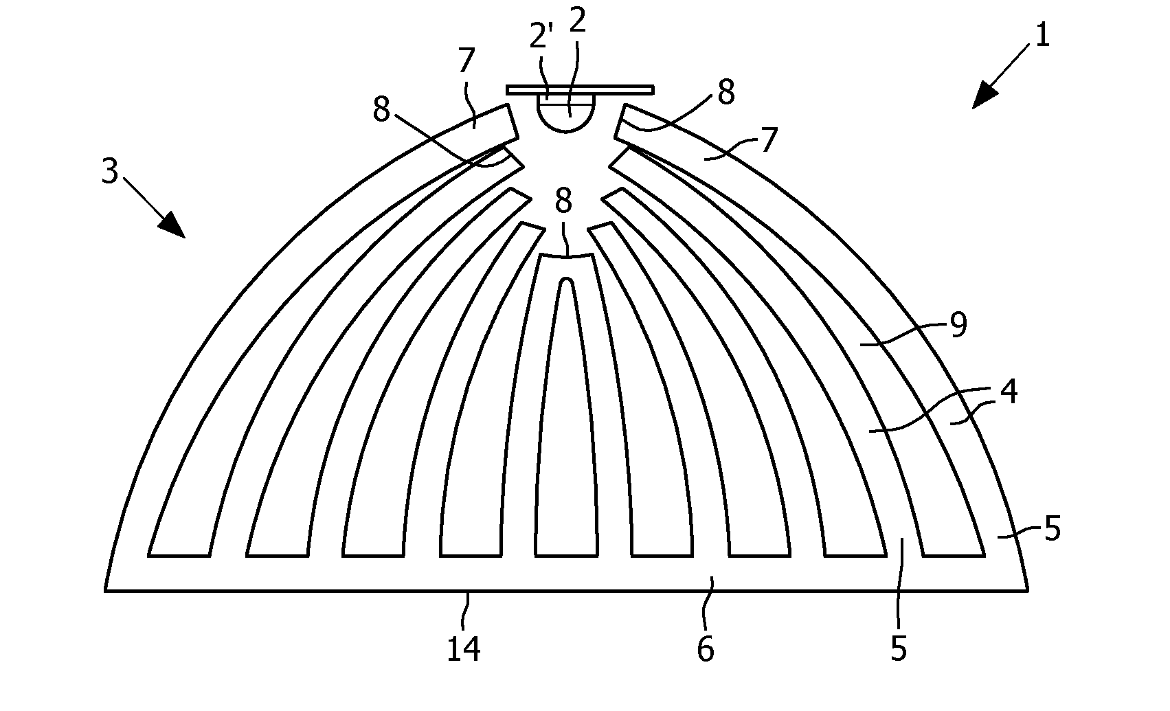
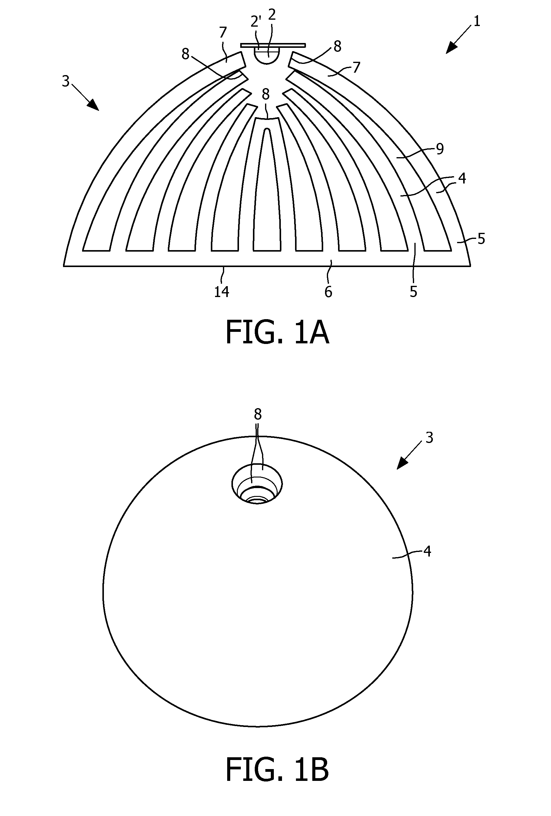
[0040]FIGS. 1A, 1B and 2 show a lighting device 1 according to the invention. The lighting device 1 comprises a high power LED 2 as light source and a lens 3. The lens 3 comprises a number of elongated light guiding elements 4 which are interconnected near spaced apart second ends 5 by means of a plate 6. First ends 7 of the elongated light guiding elements are located near the LED 2. The first ends 7 are spaced apart, such that the distance between the first ends 7 is much smaller than the distance between the second ends 5 at the plate 6. The elongated light guiding elements 4 are cup-shaped, such that both the first ends 7 and the second ends 5 form ring-shaped strips. The first ends 7 of the elongated light guiding elements 4 are each provided with a light receiving surface 8. The light receiving surfaces 8 of all the elongated light guiding elements 4 form a light entrance surface of the lens 3. The light receiving surfaces 8 are located with respect to each other in a manner s...

second embodiment

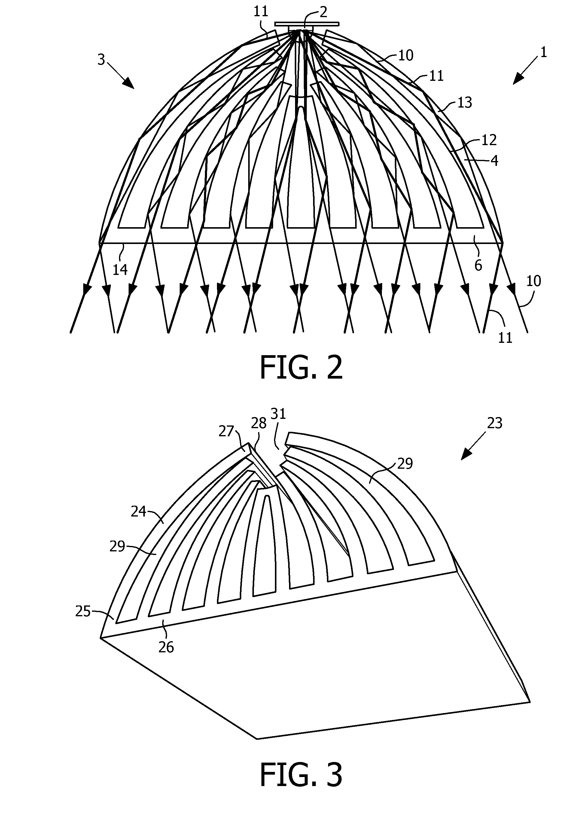
[0043]FIG. 3 shows a lens 23 of a lighting device according to the invention. The lens 23 has a similar cross section as the lens 3 and as shown in FIG. 1. However, instead of a round shape, the lens 23 has a more rectangular shape. The lens 23 comprises a number of strip-shaped elongated light guiding elements 24 extending parallel to each other. The elongated light guiding elements 24 are interconnected near second ends 5 by means of a rectangular plate 26. First ends 27 of the elongated light guiding elements 24 are located near a passage 31 into which a number of LEDs 2 can be positioned in a row or array. The first ends 27 are spaced apart, the distance between the first ends 27 being much smaller than the distance between the second ends 25, i.e. at the location where the second ends enter the plate 26. The first ends 27 of the elongated light guiding elements 24 are each provided with a light receiving surface 28, the light receiving surfaces 28 of all the elongated light gui...

third embodiment

[0047]FIGS. 4A and 5 show a lens 33 of a lighting device according to the invention. The lens 33 comprises cup-shaped curved elongated light guiding elements 34. First ends 37 of the elongated light guiding elements 34 are located against each other and form a light entrance surface 36. Second ends 35 of the elongated light guiding elements 34 are spaced apart, such that the distance between the second ends 35 is much larger than the distance between the first ends 37. Between the elongated light guiding elements 34 openings 39 are located. Near the second ends 35 the elongated light guiding elements 34 are provided with light exit surfaces 38, such that the light exit surface of the lens 33 is formed by the area in which the light exit surfaces 38 are located. The area of the light entrance surface 36 is much smaller than the area of the light exit surface 38 of the lens 33 due to which the perceived luminance of the lighting device is much lower than the luminance of the LED 2 pos...


PUM


Abstract

A lighting device (1) comprises a light source (2) and a lens (3, 23, 33, 43, 53, 63) positioned in front of the light source (2). The lens (3, 23, 33, 43, 53, 63) is provided with a light entrance surface on a side facing the light source (2) and a light exit surface (14, 38) on a side remote from the light source (2). The lens (3, 23, 33, 43, 53, 63) comprises a number of strip-shaped interconnected elongated light guiding elements (4, 24, 34, 54, 64), of which first ends (7, 27, 37, 57) and spaced apart second ends (5, 25, 35, 55, 65) comprise the light entrance surface and light exit surface, respectively. Light beams emitted by the light source (2) are transmitted by total internal reflection in the elongated light guiding elements (4, 24, 34, 54, 64) from the first ends (7, 27, 37, 57) to the spaced apart seconds ends (5, 25, 35, 55, 65).

Description

FIELD OF THE INVENTION[0001]The invention relates to a lighting device comprising a light source and a lens positioned in front of the light source, which lens is provided with a light entrance surface on a side facing the light source and a light exit surface on a side remote from the light source.[0002]The invention also relates to a lens.BACKGROUND OF THE INVENTION[0003]Such a lighting device, which is known from EP 2009345 A2, comprises a lens having a first optical refractive element arranged around a peripheral edge and a second optical refractive element centrally located on the lens. Between the light source, such as a light emitting diode (LED), and the lens a reflector is located. A forward emitted portion of the light of the LED goes directly to the lens whilst a sideward emitted portion is reflected by the reflector before it goes to the lens.[0004]A disadvantage of this known lighting device is that the perceived luminance of the lens is of the same order as the luminan...

Claims


Application Information

Patent Timeline
IPC IPC(8): G02B6/00F21V7/00F21V5/04
CPCF21V5/00G02B6/0075G02B6/0001F21V7/0091
Inventor HOLTEN, PETRUS ADRIANUS JOSEPHUSTORDINI, GIORGIA
Owner SIGNIFY HLDG BV
Why Eureka
Try Eureka