Self adjusting bearing used on ct gantry

a self-adjusting bearing and ct gantry technology, applied in the field of ct gantry, can solve the problems of increasing the total cost of the icv in the ct system, increasing the cost of the ct main bearing, and the ct main bearing is a slewing bearing with a complicated structure, so as to reduce the cost of the ct system, reduce the failure rate, and simple structure

Active Publication Date: 2012-06-14
GE MEDICAL SYST GLOBAL TECH CO LLC
View PDF14 Cites 17 Cited by
  • Summary
  • Abstract
  • Description
  • Claims
  • Application Information

AI Technical Summary

Benefits of technology

[0011]The self adjusting bearing can provide many benefits. Firstly, it will significantly reduce cost of the CT system by using small self adjusting bearings to replace a big slewing bearing. Secondly, the self adjusting bearings have a simple structure and can cooperate with common bearings in industry. These common bearings can be purchased from local or global suppliers easily. Thirdly, the self adjusting bearing eliminates an overturn moment in the existing main bearing and as a result will have a lower failure rate. Finally, in case of bearing failure, the self adjusting bearings can be replaced in the field, thus eliminating the need to replace the whole gantry or CT system.

Problems solved by technology

However, the main bearing of a current CT gantry has many drawbacks.
First, the current CT main bearing is expensive, which increases the total cost of the ICV in the CT system.
Second, the CT main bearing is a slewing bearing with a very complicated structure.
Most of the bearings are purchased from abroad, which have a long lead time, and are difficult for localization.
Third, the main bearing and the rotating base are in a cantilever beam structure, which creates a significant overturn moment of the main bearing.
This results in a high failure rate and low resistance for vibration and shock during shipment and handling of the main bearing.
Finally, the failure of the main bearing, such as noise and screw skip issues, in the field leads to the replacement of the whole gantry or even CT system, which will necessarily increase service expenses and customer complaints.
However, these supporting rollers having a cylindrical shape cannot limit the rotating base's movement in the Z-direction perpendicular to the scanning plane.
This will increase material wear of the resilient rollers and the rotating base.

Method used


Image

  • Self adjusting bearing used on ct gantry
  • Self adjusting bearing used on ct gantry
  • Self adjusting bearing used on ct gantry

Examples


Embodiment Construction

[0030]The following detailed description is provided with reference to figures which schematically show exemplary embodiments. These embodiments are described in sufficient detail as to enable those skilled in the art to carry them out and to make structural changes through combinations thereof or with other embodiments, without departing from the scope of the embodiments described herein. Therefore, the following detailed description shall not be construed as limiting the present invention.

[0031]As used herein, unless otherwise indicated, the term “a” or “an” indicates one or more, and the terms “comprising”, “including”, and “having” indicate the existence of further element(s) in addition to those listed.

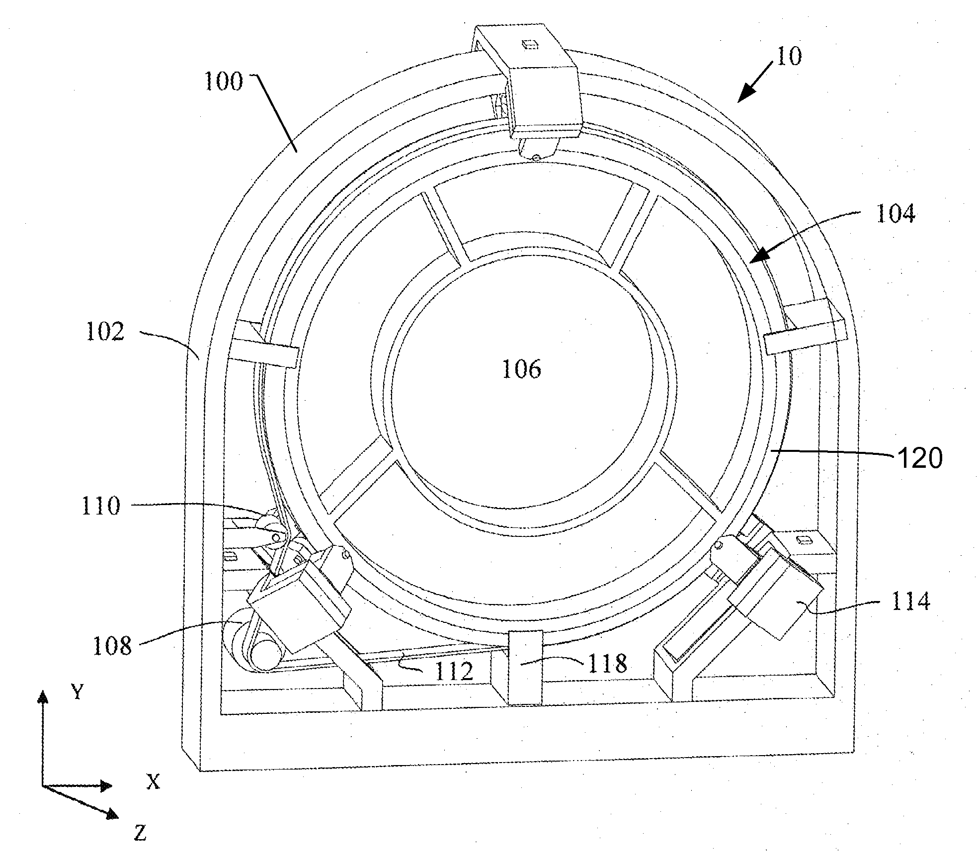
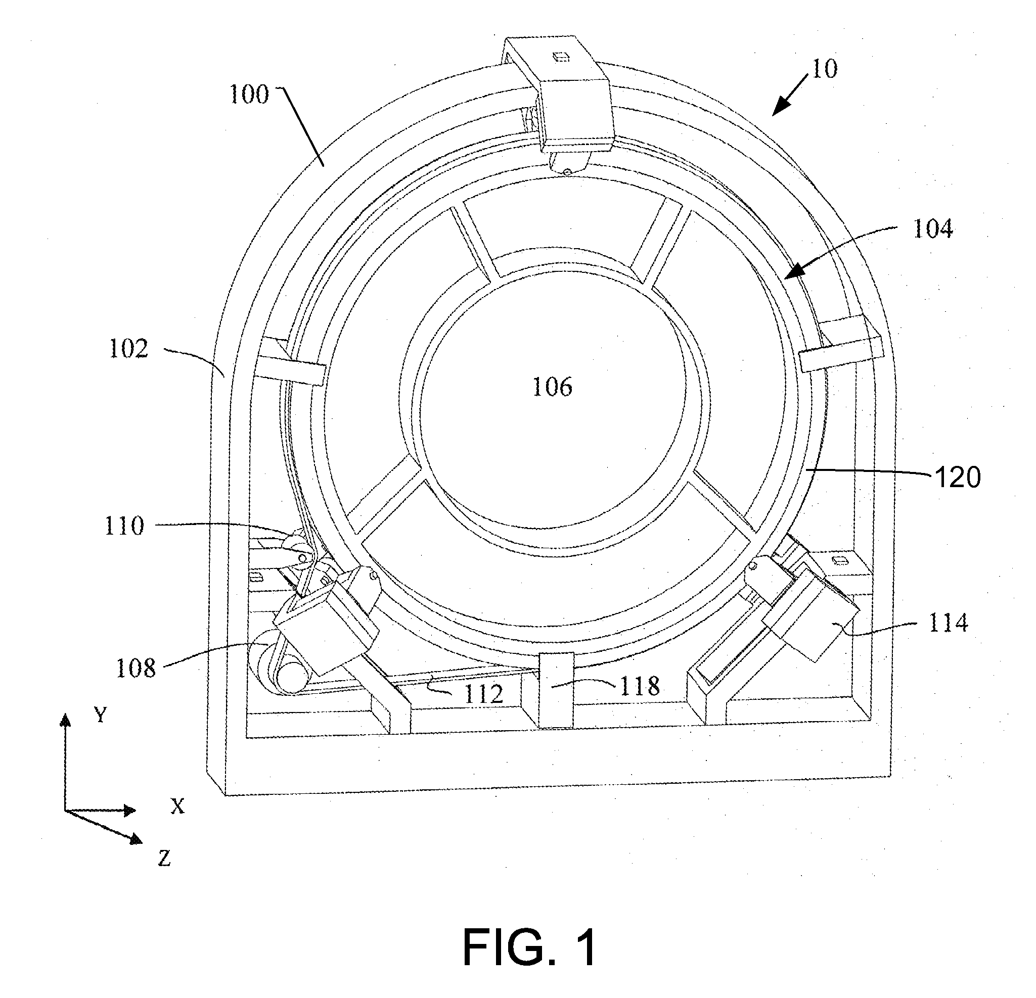
[0032]FIG. 1 is a perspective view of a CT system 10 according to an exemplary embodiment. The CT system 10 has a CT gantry 100 including a main frame 102 and a rotating base 104. The rotating base 104 has a scanning chamber 106 for receiving a human body to be scanned by the CT ...


PUM


Abstract

A self adjusting bearing for use on a CT gantry is provided. The self adjusting bearing is configured to be mounted on a main frame of the CT gantry and is configured to support a rotating base of the CT gantry wherein the self adjusting bearing includes a roller, a first component, and a second component, the roller is configured to support the rotating base and is rotatably mounted on the first component, the second component is configured to be mounted on the main frame, and the first component and the second component are configured to rotatably engage each other such that they can rotate relative to each other during the mounting of the self adjusting bearing.

Description

CROSS REFERENCE TO RELATED APPLICATIONS[0001]This application claims the benefit of Chinese Patent Application No. 201010602819.7 filed Dec. 10, 2010, which is hereby incorporated by reference in its entirety.BACKGROUND OF THE INVENTION[0002]The present invention relates to a CT gantry, and more specifically to a self adjusting bearing used on a CT gantry.[0003]Current CT gantries have a main bearing, a big pulley and a rotating base for support and rotation of all rotating parts in the CT gantry. The main bearing is one of the most critical mechanical parts for the CT gantry.[0004]However, the main bearing of a current CT gantry has many drawbacks. First, the current CT main bearing is expensive, which increases the total cost of the ICV in the CT system. Second, the CT main bearing is a slewing bearing with a very complicated structure. Most of the bearings are purchased from abroad, which have a long lead time, and are difficult for localization. Third, the main bearing and the r...

Claims


Application Information

Patent Timeline
Patent Type & Authority Applications(United States)
IPC IPC(8): H05G1/02F16C13/06A61B6/03
CPCA61B6/03A61B6/44A61B6/4435F16C2316/10F16C13/04F16C19/507A61B6/4447F16C2300/14
Inventor ZHANG, XIAOYANLIU, HAILIANGLIU, ZHUOYANG, XUYONGWANG, XUELI
Owner GE MEDICAL SYST GLOBAL TECH CO LLC
Why Eureka
Try Eureka