Image forming apparatus, control method and computer-readable medium

a technology of image forming apparatus and control method, applied in the direction of electrographic process apparatus, instruments, optics, etc., can solve the problems of inability to ensure a space large enough to form a patch image, inability to accurately detect the density of toner, and inability to ensure the space large enough to install a detector, etc., to achieve the effect of eliminating the time difference between toner supply timings

Inactive Publication Date: 2012-06-14
CANON KK
View PDF1 Cites 6 Cited by
  • Summary
  • Abstract
  • Description
  • Claims
  • Application Information

AI Technical Summary

Benefits of technology

[0014]The present invention provides an image forming apparatus capable of supplying toner at an appropriate timing by adding the count value of respective pixels for each color component directly to video data of the color component and transmitting it to a printer engine to eliminate the time difference between toner supply timings.

Problems solved by technology

However, the method of detecting a toner density from a reflectance obtained when a developer conveyed on the developing sleeve or one in the developer container is irradiated with light has a problem that no toner density can be detected accurately if the detector is contaminated with scattered toner or the like.
The inductance detection ATR has a problem that a sensor detection signal corresponding to an apparent magnetic permeability changes discontinuously as the bulk density of the developer changes when the developer is left to stand or the environment varies immediately before the operation of the image forming apparatus stops or immediately after the operation restarts.
The method of controlling a toner density indirectly from a patch image density has a problem that neither a space large enough to form a patch image nor a space large enough to install a detector can be ensured as a copying machine or image forming apparatus becomes compact.
In this case, software processing by the CPU intervenes, so a development timing based on supply target video data does not match an actual toner supply operation timing.
That is, the tandem engine has a problem that a time difference in development exists between a drum arranged upstream and one arranged downstream, and if toner supply timings are adjusted to any drum, a supply target page and toner supply timing do not match each other.

Method used


Image

  • Image forming apparatus, control method and computer-readable medium
  • Image forming apparatus, control method and computer-readable medium
  • Image forming apparatus, control method and computer-readable medium

Examples


first embodiment

[0041][System Configuration]

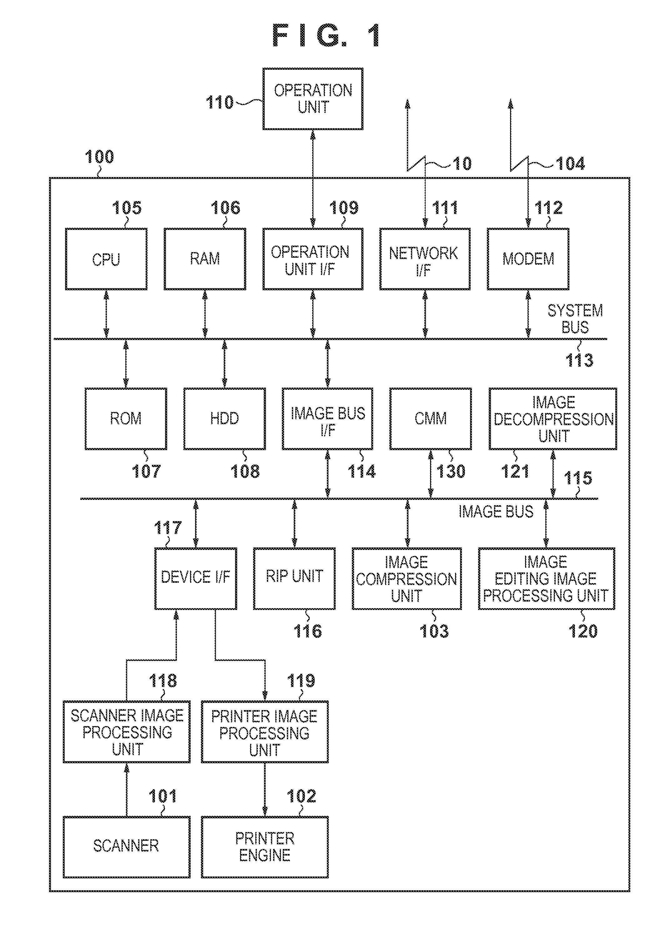
[0042]An embodiment of the present invention will now be described with reference to the accompanying drawings. FIG. 1 is a block diagram showing the whole configuration of an image processing system according to the first embodiment. Referring to FIG. 1, a scanner 101 serving as an image input device and a printer engine 102 serving as an image output device are internally connected in an image forming apparatus 100. The scanner 101 is connected to a device I / F 117 via a scanner image processing unit 118. The printer engine 102 is connected to the device I / F 117 via a printer image processing unit 119. The scanner image processing unit 118 and printer image processing unit 119 perform control to read image data and print out. The image forming apparatus 100 is connected to a LAN 10 and public line 104, and performs control to input / output image information and device information via the LAN 10.

[0043]A CPU (Central Processing Unit) 105 controls the image ...

second embodiment

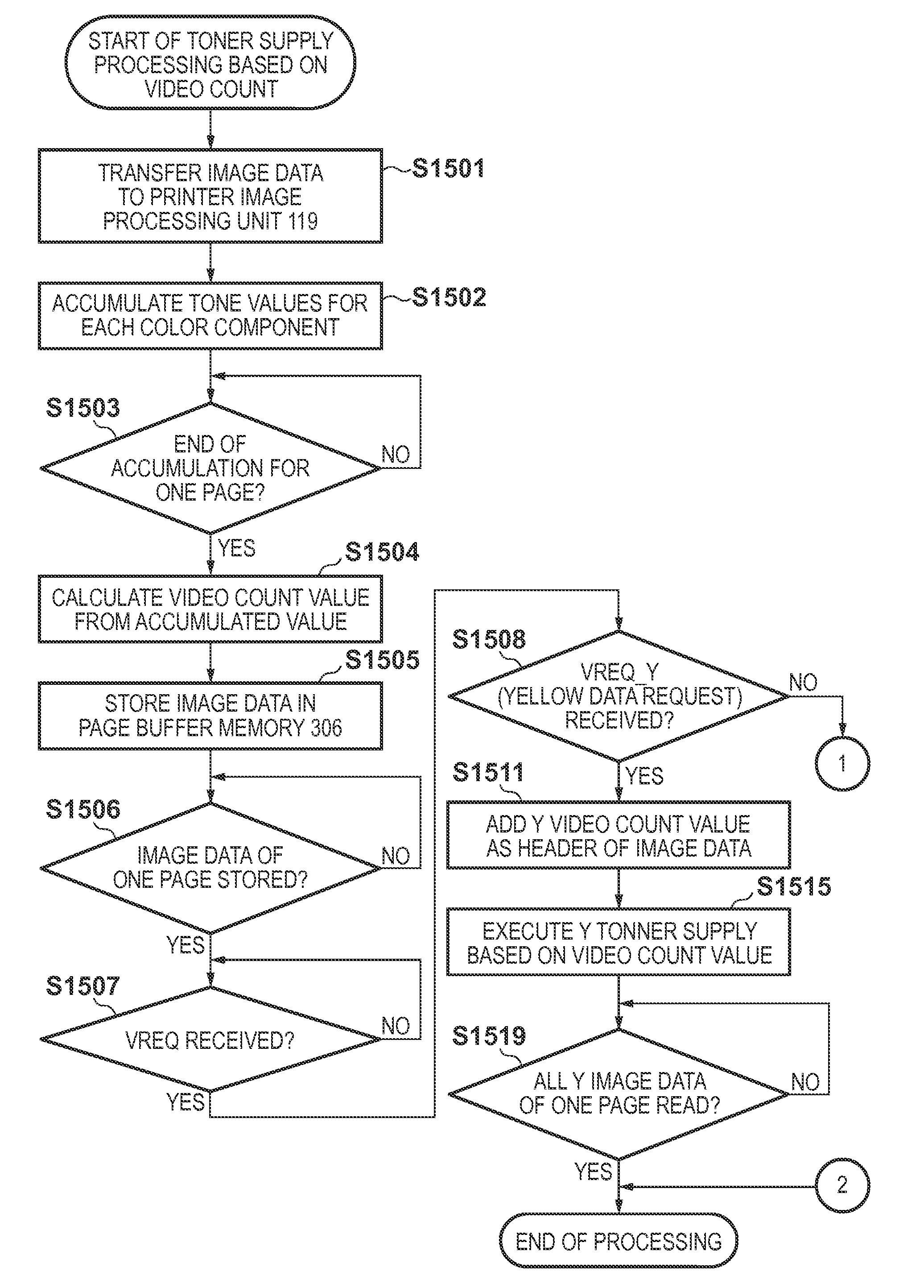
[0119]In the first embodiment, the video count is accumulated in the page unit. The second embodiment will describe a method of dividing image data of one page into a plurality of units and adding a video count for each color component in the divided unit, and toner supply control based on this method. An image forming apparatus 100 and each software module have the same arrangements as those in the first embodiment, a processing sequence up to input to a printer image processing unit 119 in a printer operation is also the same, and a description thereof will not be repeated.

[0120]In the printer operation, similar to the first embodiment, a color space conversion unit 301 converts image data input to the printer image processing unit 119 from a luminance value (RGB in this embodiment) into a density value (CMYK in this embodiment) in the above-described manner. A video count generation unit 302 accumulates the tone values (multi-level data) of respective pixels for each color compon...

third embodiment

[0146]In the first embodiment, information such as a video count is added to the header of the data format. The third embodiment will explain a method of adding a video count as a footer for each color component, and toner supply control based on this method.

[0147]An image forming apparatus 100 and each software module have the same arrangements as those in the first embodiment, a processing sequence up to input to a printer image processing unit 119 in a printer operation is also the same, and a description thereof will not be repeated.

[0148]FIG. 4 is a block diagram showing the internal arrangement of the printer image processing unit 119 in the third embodiment. In the third embodiment, a video count insertion unit 401 is arranged at the succeeding stage of a halftone processing unit 304. An inter-drum delay memory control unit 305 is arranged at the succeeding stage of the video count insertion unit 401. In the third embodiment, the printer image processing unit 119 does not inc...


PUM


Abstract

An image forming apparatus including a developing device corresponding to a color component, comprises: a conversion unit configured to accumulate, for each color component, values of respective pixels for each color component that fall within a predetermined range of image data, and to convert the accumulated value into a count value of the color component; an addition unit configured to add, to the image data, the count value of each color component that has been converted by the conversion unit; and a control unit configured, when forming an image based on the image data, to supply toner to the developing device of each color component in accordance with the count value of the color component that has been added by the addition unit.

Description

BACKGROUND OF THE INVENTION[0001]1. Field of the Invention[0002]The present invention relates to an image forming apparatus and control method for performing toner supply control using a video count, and a computer-readable medium.[0003]2. Description of the Related Art[0004]A developing device in an image forming apparatus of an electrophotographic type or electrostatic printing type generally adopts a two-component developer mainly containing toner particles and carrier particles. Especially, most developing devices in color image forming apparatuses for forming a full-color or multi-color image by an electrophotographic method use a two-component developer in terms of image tint and the like. The toner density (that is, the ratio of the weight of the toner particles to the total weight of the carrier particles and toner particles) of the two-component developer is a very important factor to stabilize the image quality. The toner particles of the developer are consumed in developm...

Claims


Application Information

Patent Timeline
Patent Type & Authority Applications(United States)
IPC IPC(8): G03G15/08
CPCG03G15/0121G03G15/0189G03G15/553G03G15/5079G03G15/556
Inventor YAMADA, NAOTO
Owner CANON KK
Why Eureka
Try Eureka