Axial coupling with compensated forces

a technology of axial coupling and compensating forces, which is applied in the direction of machines/engines, braking systems, gearing, etc., can solve the problems of high cost of control and require a considerable sensor system, and achieve the effect of reducing control expenditur

Inactive Publication Date: 2012-06-14
DANFOSS POWER SOLUTIONS INC
View PDF2 Cites 2 Cited by
  • Summary
  • Abstract
  • Description
  • Claims
  • Application Information

AI Technical Summary

Benefits of technology

[0007]The object underlying the invention is to provide a drive train of a hydraulic drive of a driveable operating machine, which drive train is constructed in a simpler manner than known systems and which requires reduced expenditure on control for coupling operations when connecting or disconnecting hydraulic machines to or from the drive train. In addition, the drive train is to be developed in a sturdy manner and is to be able to be produced in a cost-efficient manner.
[0014]Acting on the hydraulic machine and the actuating mechanism of the coupling with the same hydraulic pressure causes the transmittable torque on the friction coupling to be controlled automatically without any need for an expensive regulating device or control unit. The higher the torque to be transmitted is to be, the greater the contact pressure on the two friction surfaces has to be, irrespective of the speeds of the motor and consumer or transmission.
[0027]It is obvious that the supply of hydraulic fluid to the hydraulic machine and possibly also to the coupling has to take place by means of lines, which allow movement at least to the order of magnitude of the switching path of the coupling. In this case, the coupling is preferably supplied with the operating pressure of the hydraulic machine, both the supply of hydraulic fluid to the hydraulic machine and to the coupling being effected by means of suitable valves in an almost isochronous manner and at identical pressure. This means the disadvantages that occur in the prior art of expensive control for the coupling engagement operation in conjunction with the force transmission are avoided. According to the invention, the hydraulic pressure prevailing in the pressure chamber of the coupling is identical to that in the hydraulic machine, which can be accomplished by means of simple directional control valves, for example to avoid hydraulic short circuits.
[0028]The contact force achieved in the engaged state between the, for example, conical friction surfaces of the coupling follows the pressure in the pressure chamber, which preferably corresponds to the operating pressure of the hydraulic machine which is to be coupled. The necessary inflow of hydraulic fluid is preferably branched off the hydraulic fluid line of the hydraulic machine. The achievement here is that the contact force rises as the load on the hydraulic machine increases, which prevents the coupling slipping through. This means that a secure transmission of even high torques is ensured and wear is reduced.

Problems solved by technology

A disadvantage of the known drive train of the described type is that when the hydraulic machine or the hydro-motor is reconnected in the above-mentioned prior art and as a result the drive train is engaged, on account of the conventionally used synchronous couplings the hydraulic machine has first to be accelerated in order to reach the necessary synchronous speed for the coupling engagement.
In this case, there is dependence on the operating pressure of the hydraulic drive and on the required speed, which makes control expensive and requires a considerable sensor system.
However, this cannot take place until after engagement, so that the speed of the hydraulic machine does not increase beyond that of the consumer or come to a standstill if the torque set is insufficient.
Over and above this, the expensive and complicated control requires the engagement operation to be coordinated in time, said engagement operation not then always taking place smoothly in a manner that protects the materials.
In a corresponding manner, this is often monitored by a complicated system of sensors.

Method used


Image

  • Axial coupling with compensated forces
  • Axial coupling with compensated forces
  • Axial coupling with compensated forces

Examples


Embodiment Construction

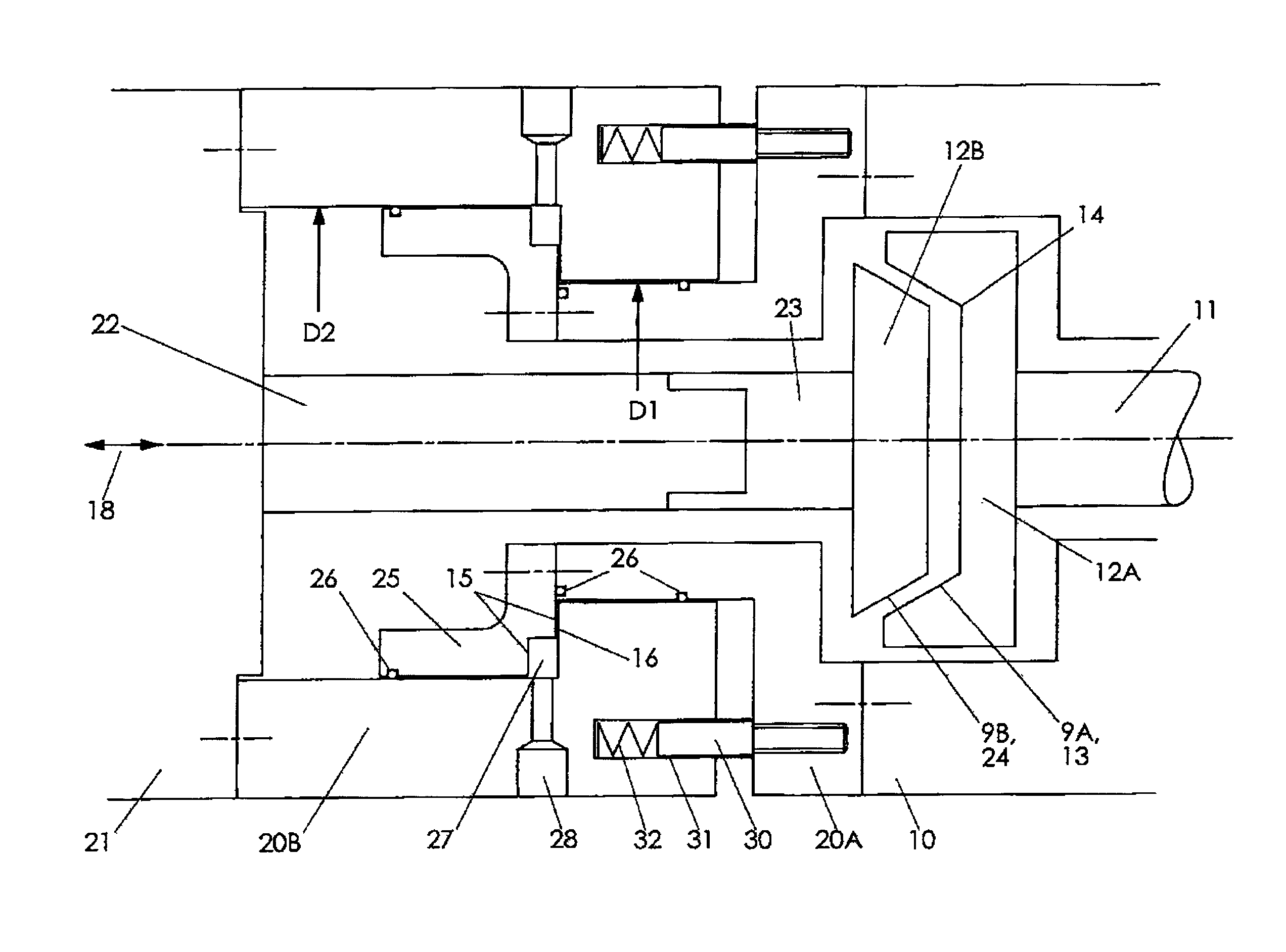
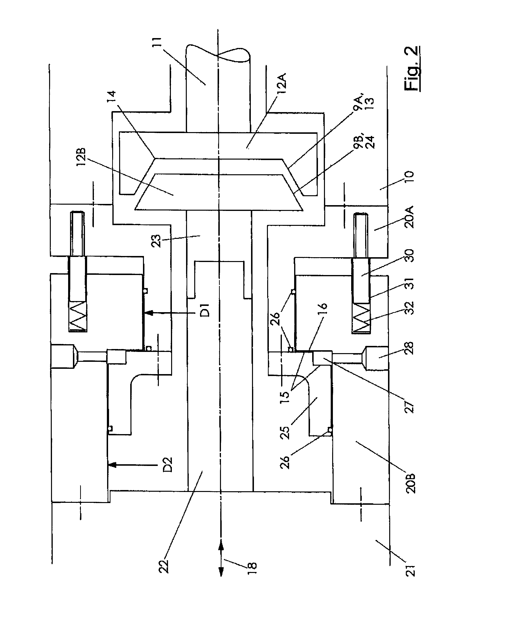
[0035]The embodiments described below are shown in an exemplary manner as connectable hydraulic units by way of a hydraulic motor, but are also applicable in an analogous manner to connectable hydraulic pumps, it being possible to realize both types of hydraulic machines as fixed displacement units or variable displacement units, the direction of rotation of which is reversible. In this case, hydraulic units which can act both as pump and as motor are also included.

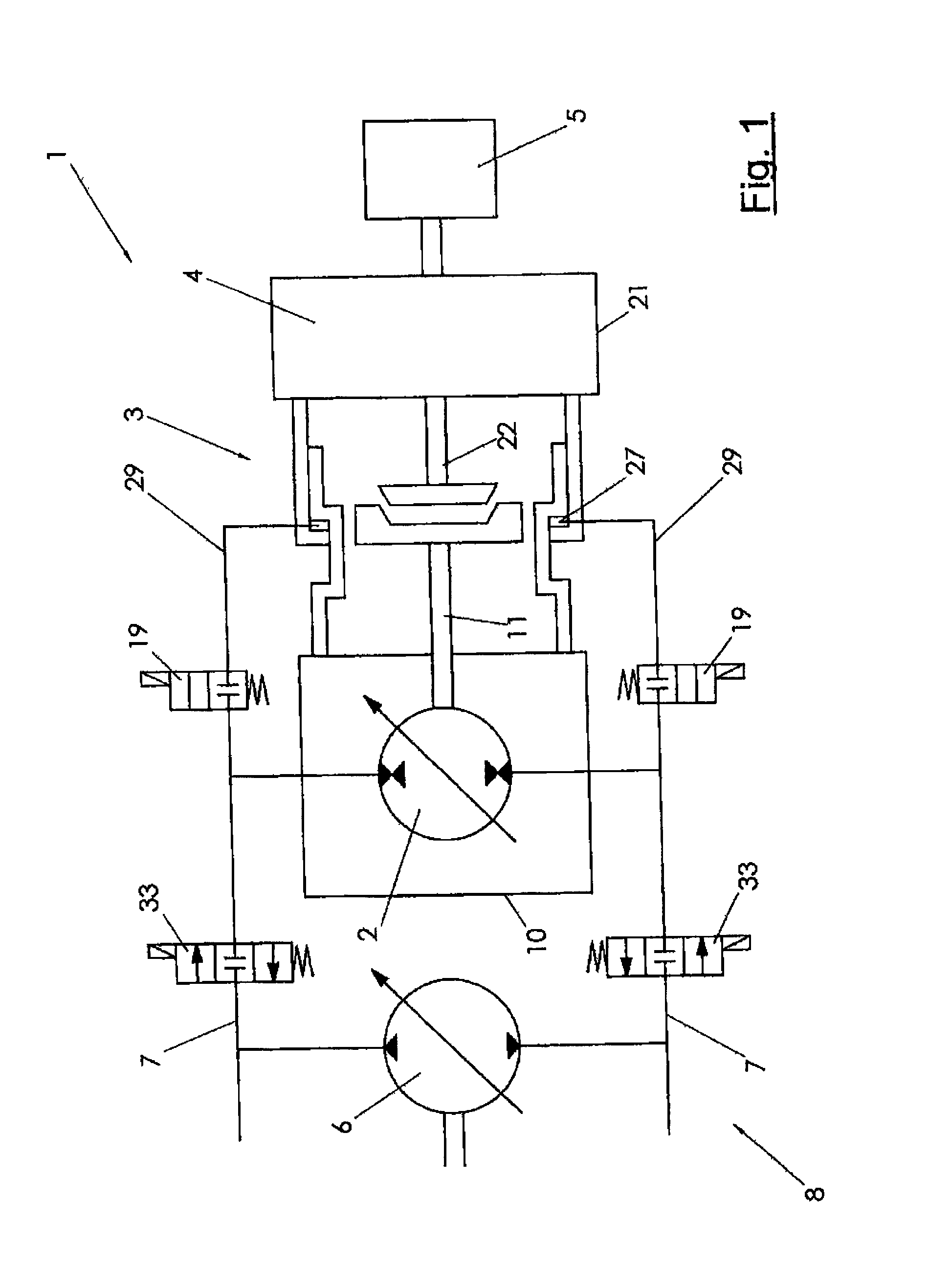
[0036]FIG. 1 is a strongly schematic representation of a drive train 1 according to the invention which is part of a drive system of an operating machine with a hydraulic drive. The drive train includes, for example, a motor 2 which is preferably realized as a variable displacement hydro-motor and which is supplied with hydraulic fluid (hydraulic oil) by a variable displacement pump 6. The variable displacement pump 6 is, for example, driven by an internal combustion machine (not shown) and supplies a flow of hydraulic fl...


PUM


Abstract

The invention relates to a drive train (1) for a hydraulic drive where a friction coupling (3) is arranged between a hydraulic machine (2) and a consumer (5). The coupling (3) has two parts (20A, 20B) which are displaceable towards each other in the axial direction (18) and are connected to the hydraulic machine (2) or to the consumer (5). Hydraulic fluid is introduced by means of a pressure line (28) into a pressure chamber (27) formed between the parts (20A, 20B), as a result of which the complementarily formed friction surfaces (9A, 9B) become frictionally locked together and a torque is able to be transmitted between the hydraulic machine (2) and the consumer (5). The friction surfaces (9A, 9B) are each fixedly connected at least radially to the shaft of the hydraulic machine (2) or of the consumer (5).

Description

BACKGROUND OF THE INVENTION[0001]The invention relates to a drive train of a hydraulic drive according to the preamble of claim 1.[0002]Drive trains of the generic type are often used in hydraulically driven, driveable operating machines, such as are known, for example, from DE 44 31 864 A1. In the case of such high-performance drives, the requirement is to reach high travelling speeds as well as a high level of tractive force with high levels of efficiency. Drives with two hydro-machines are increasingly being used for this purpose nowadays, both of which, as a rule, are adjustable. Examples for this are provided by DE 195 10 914 A1 and DE 43 07 616.[0003]In this case, both hydro-motors are driven by a common hydro-pump and, as regards the circuit of the hydraulic fluid, are connected in parallel. The one hydro-motor can be adjusted to zero displacement to achieve a high travelling speed. This hydro-motor is then disengaged to avoid high flange losses, i.e. it goes to zero r.p.m. S...

Claims


Application Information

Patent Timeline
Patent Type & Authority Applications(United States)
IPC IPC(8): F01D15/12
CPCB60T13/20B60T8/368B60K17/02F16D25/0632F16H47/02
Inventor WIDEMANN, AXEL
Owner DANFOSS POWER SOLUTIONS INC
Why Eureka
Try Eureka