
External fixation apparatus with angularly adjustable drill guiding and pin clamping means

a fixation apparatus and angular adjustment technology, applied in bone drill guides, medical science, surgery, etc., can solve problems such as pain, long period of stiffness and disability, deformation,

Active Publication Date: 2012-06-14
NUTEC ORTHOPEDICS
View PDF9 Cites 20 Cited by
  • Summary
  • Abstract
  • Description
  • Claims
  • Application Information

AI Technical Summary

Benefits of technology

[0005]External fixation often provides the best method for holding bone fragments in place during he healing of a severe bone fracture, in which multiple bone fragments are formed. In the external fixation process, bone pins or wires ate surgically attached to the individual bone fragments and to intact sections of bone, so that a desired alignment of multiple fragments can be maintained during the healing process. The individual bone pins or wires are also

Problems solved by technology

A problem with this method is that it sometimes results in inadequate internal fixation, which can cause deformity, pain, and prolonged disability.
While this type of fixation often provides an improvement over conventional casting techniques in the management of severe fractures of the distal radius, immobilization of the radiocarpal joint during the treatment period typically results in a long period of stiffness and disability after the external fixation device is removed.
One problem associated with the installation of bone pins for external fixation arises from the potential damage to soft tissues, including muscles, nerves, and ligaments disposed between the surface of the skin and the bone.

Method used


Image

  • External fixation apparatus with angularly adjustable drill guiding and pin clamping means
  • External fixation apparatus with angularly adjustable drill guiding and pin clamping means
  • External fixation apparatus with angularly adjustable drill guiding and pin clamping means

Examples


first embodiment

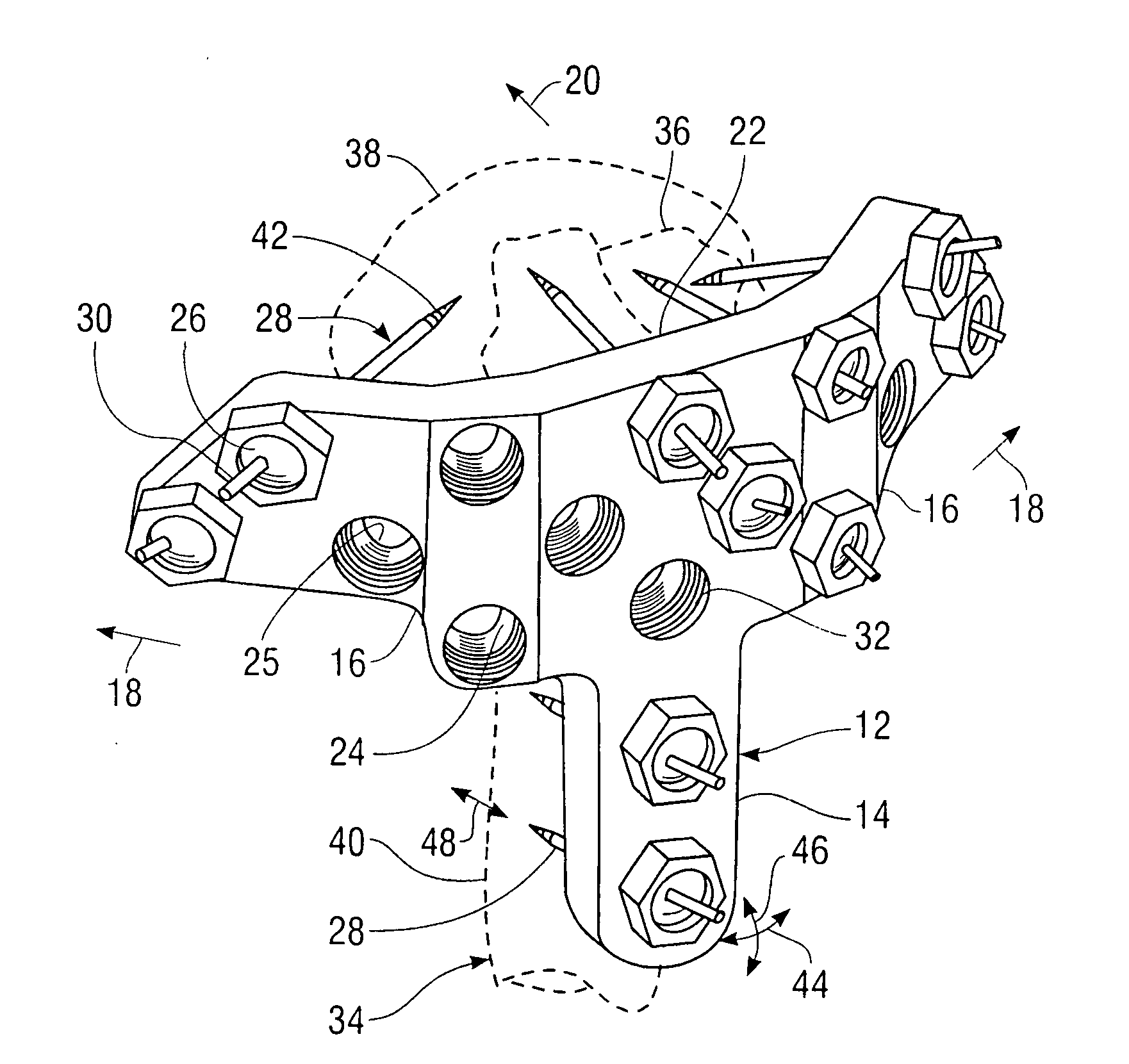
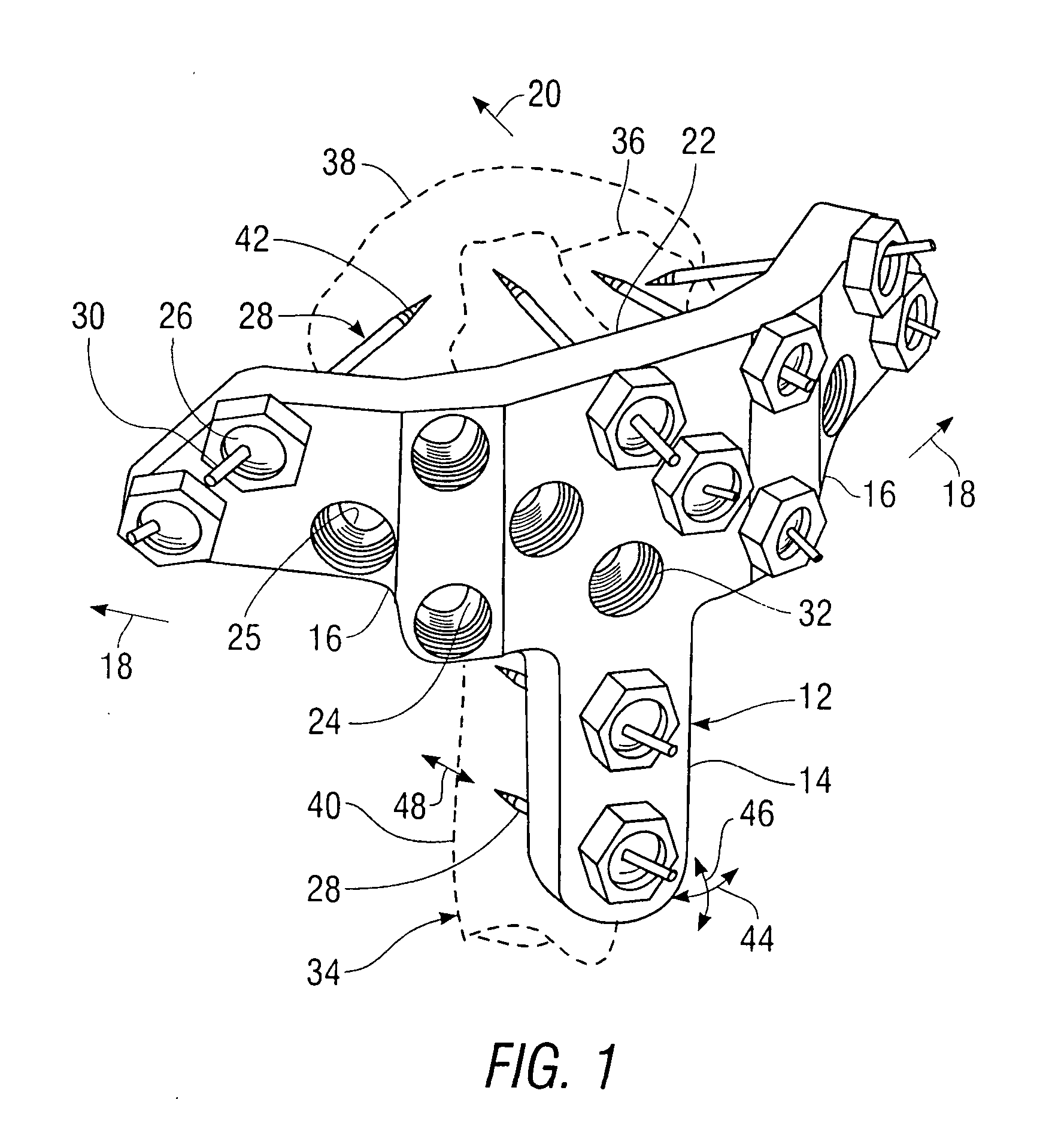
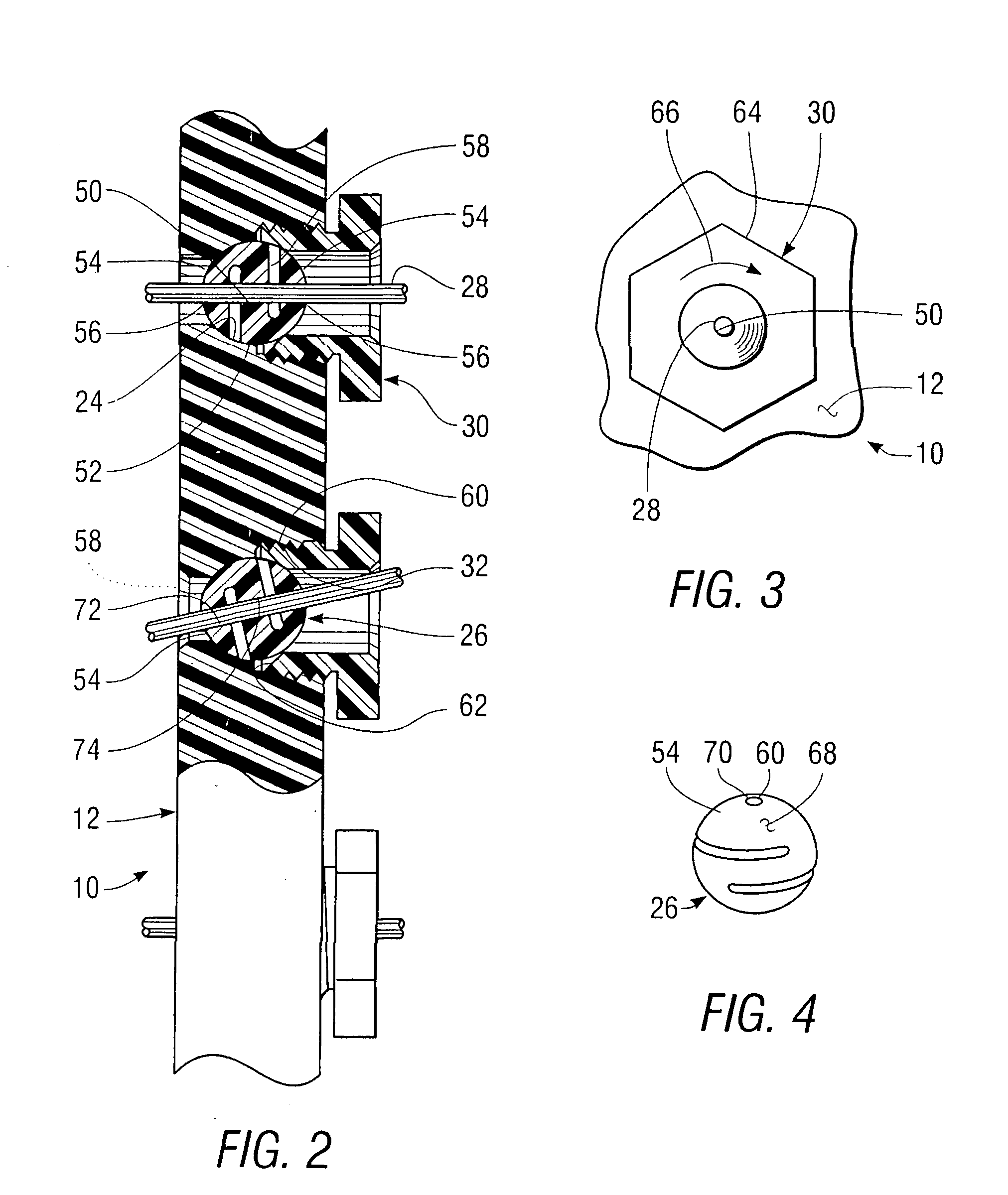
[0043]FIG. 1 is a perspective view of a device 10 for the external fixation of bone fragments, built in accordance with the invention. The device 10 includes a housing 12 having a vertically elongated central portion 14 and a lateral portion 16 extending outward, in the directions of arrows 18, and rearward, in the direction of arrow 20, from each side of an upper end 22 of vertically elongated central portion 14: The vertically elongated central portion 14 includes a first plurality of the internal mounting surfaces 24; each of which extends outwardly from an aperture 25 within the housing 12, while each lateral portion 16 includes at least one of the internal mounting surfaces 24 extending from an aperture 25. Some of the internal mounting surfaces 24 mount pin holders 26 holding bone pins 28, with the pin holders 28 being held in place by clamping members 30 engaging threaded surfaces 32 of the housing 12. This arrangement provides for the placement of bone pins 28 at various lev...

second embodiment

[0050]FIG. 5 is a side elevation of a device 80 for external fixation of bone fragments, built in accordance with the invention and shown with pins 82 attached to several fragments of bones 84 within a finger 86. The device 80 includes a housing 88, having a plurality of apertures 90 through which the pins 82 extend, and a first clamping member 92, which is turned to clamp the pins 82 in place within the housing 88.

[0051]Features of the device 80 will now be discussed with reference being made to FIGS. 6 and 7. FIG. 6 is a plan view of the device 80, while FIG. 7 is a cross-sectional side elevation thereof. The housing 88 includes a single internal mounting surface 94, with the single clamping member 92, clamping each of a plurality of pin holders 96 in place within the first internal mounting surface 94 and deflecting a deformable portion 98 of each of the pin holders 96 to hold the bone pin 82 therein in place. For example, the first internal mounting surface 94 is formed as an el...

third embodiment

[0058]FIG. 11 is a perspective view of a device 200 built in accordance with the invention for the external fixation of fragments 201 within a fractured distal end 202 of a radius 203. The device 200 includes an elongated shank mounting section 204, a fragment attachment pin array section 206, and a lateral fragment mounting section 208. The elongated shank mounting section 204 includes an angularly adjustable shank mounting pin 210 extending downward, in the direction of arrow 211, to be fastened into a shank portion 212 of the distal radius 202 and a linearly adjustable shank mounting pin 216, also extending downward, in the direction of arrow 211, to be fastened into the shank portion 212. The fragment attachment pin array section 206 includes a plurality of attachment pins 218 extending downward, in the direction of arrow 211, to be fastened into a number of the bone fragments 201. The lateral fragment mounting section 208 includes a number of angularly adjustable fragment mount...


PUM


Abstract

An external fixation device for holding bone fragments in place includes a housing having a number of rotationally adjustable pin holders, each of which is held by a clamping member that simultaneously clamps the pin holder within an internal mounting surface of the housing and a bone pin within the pin holder. For example, the device includes a number of internal mounting surfaces, each of which can include a single pin holder. A drill guide fitting into the internal mounting surfaces is used to protect soft tissue from bone pins and they are rotated during installation.

Description

CROSS-REFERENCE TO A RELATED APPLICATION[0001]This is a continuation-in-part of a copending U.S. patent application Ser. No. 12 / 460,680, filed Jul. 23, 2009, for which a notice of allowance has been received, which is a continuation-in-part of U.S. patent application Ser. No. 11 / 893,582, filed Aug. 16, 2007, issued as U.S. Pat. No. 7,717,916 B2.BACKGROUND OF THE INVENTION[0002]1. Field of the Invention[0003]This invention relates to apparatus for the external fixation of fractured bones, and, more particularly, to such apparatus having means for adjustably mounting and clamping a number of bone pins to a housing, and to such an apparatus including a drill guide used to prevent contact between a bone pin that is rotated during installation and soft tissue.[0004]2. Summary of the Background Art[0005]External fixation often provides the best method for holding bone fragments in place during he healing of a severe bone fracture, in which multiple bone fragments are formed. In the extern...

Claims


Application Information

Patent Timeline
IPC IPC(8): A61B17/64
CPCA61B17/171A61B2017/1782A61B17/6491A61B17/645A61B17/1782
Inventor HAJIANPOUR, MOHAMMED A.
Owner NUTEC ORTHOPEDICS
Learn More