
Calculating Liquid Levels in Arbitrarily Shaped Containment Vessels Using Solid Modeling

a technology of liquid level and arbitrarily shaped containment vessels, applied in cad techniques, instruments, machines/engines, etc., can solve problems such as inability to provide accurate solutions, complex, and difficult to maintain and enhance, and achieve the effect of eliminating data conversion problems

Active Publication Date: 2012-06-14
THE BOEING CO
View PDF7 Cites 19 Cited by
  • Summary
  • Abstract
  • Description
  • Claims
  • Application Information

AI Technical Summary

Benefits of technology

The present invention is about a system and method for calculating liquid levels in complex-shaped containers using solid modeling and boolean operations. The system uses a boundary representation of the container to determine the liquid level based on the volume of liquid and the orientation of the container. The system is designed to be embedded in other software solutions and can be used in different applications such as fuel tanks in aircraft and automobiles. The software operates directly on geometry, eliminating data conversion issues and approximations. The technical effects of the invention include reducing the amount of code needed and simplifying the computation of liquid levels and other properties of the container.

Problems solved by technology

That known solution has the following disadvantages: (1) it is tied to a specific geometric shape and topology (i.e., a wing); (2) it requires extensively formatted and reduced geometric representations of structural inputs to function; (3) it uses approximate solution methods and therefore does not provide an accurate solution; (4) the existing software is written in FORTRAN, which is complex, hard to maintain and hard to enhance; (5) the existing software is hard to integrate with other solutions (e.g., computation of an airplane's center of gravity subject to different flight angles); (6) analysis results are exchanged through proprietary file formats that require custom coding to read and write.

Method used


Image

  • Calculating Liquid Levels in Arbitrarily Shaped Containment Vessels Using Solid Modeling
  • Calculating Liquid Levels in Arbitrarily Shaped Containment Vessels Using Solid Modeling
  • Calculating Liquid Levels in Arbitrarily Shaped Containment Vessels Using Solid Modeling

Examples


Embodiment Construction

[0034]Various embodiments of a system for modeling and simulating the behavior of liquid inside a fuel tank under dynamic conditions will now be described.

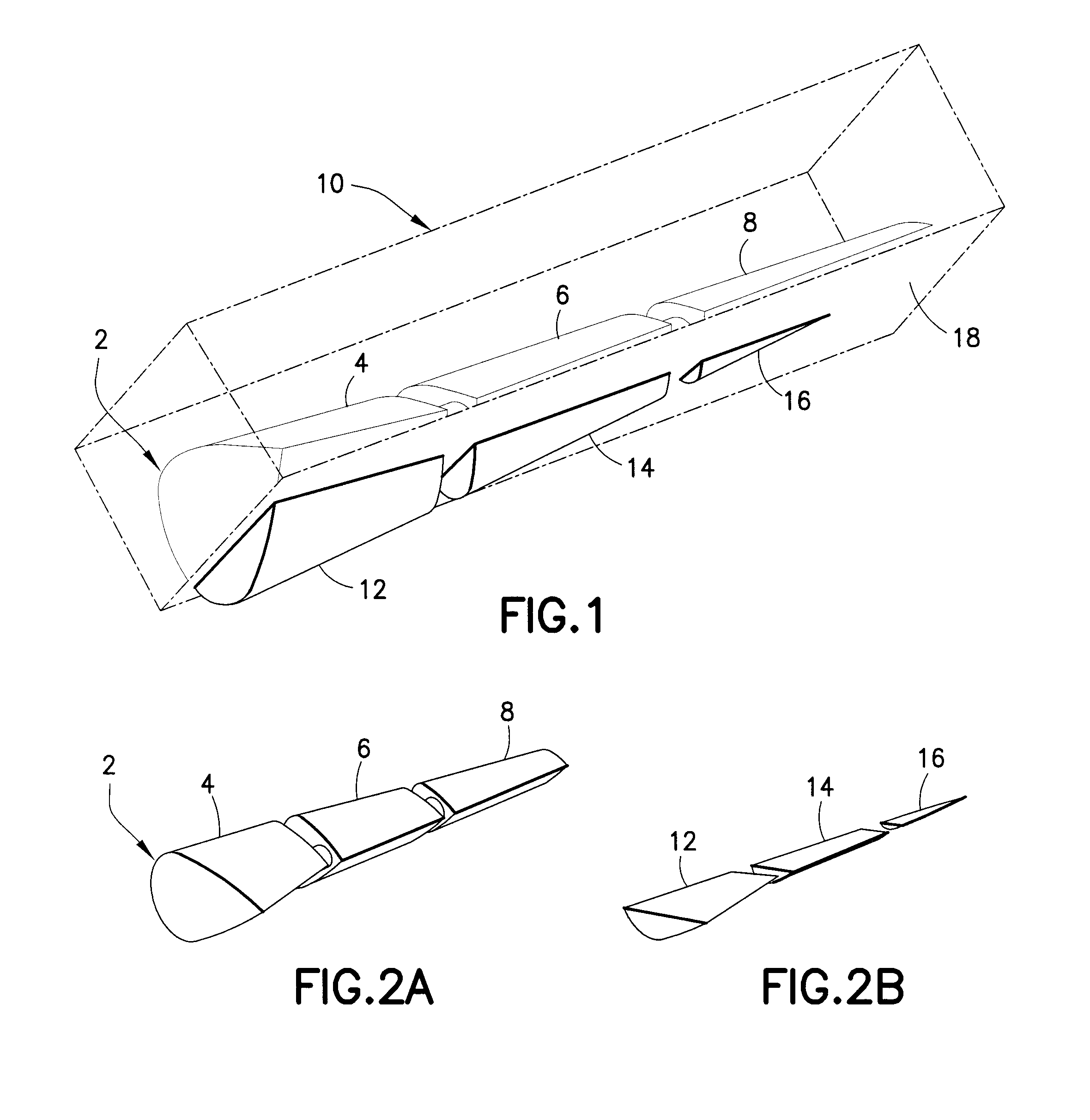
[0035]FIG. 1 is a solid model representation of a wing 2 comprising compartments 4, 6 and 8 for storing fuel. In accordance with one embodiment of the invention, the solid model representation of wing 2 is intersected by a face 18 of an infinite horizontal half-space 10, which face 18 represents the level of fuel (i.e., the level of the surface plane of the fuel) inside the wing 2 given a 15% volume fill. An angled viewpoint was chosen for clarity.

[0036]As shown in FIG. 2A, compartment 4 of wing 2 is in fluid communication with compartment 6 via an orifice, and compartment 6 is in fluid communication with compartment 8 via an orifice. FIG. 2A shows wing 2 with a 0° bank angle. In contrast, FIG. 2B is a solid model representation of the volumes of fuel inside the wing 2 at a 0° bank angle for a 15% volume fill. As seen in FIG. 2B, ...


PUM


Abstract

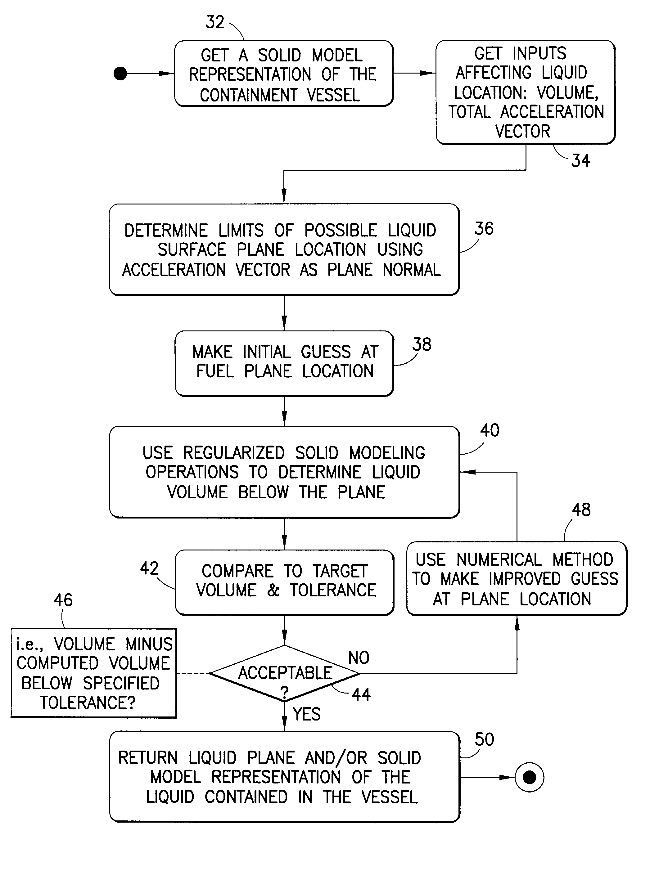
Systems and method for simulating liquid containment behavior. The system comprises a solid modeler and a nonlinear equation solver. The nonlinear equation solver takes as input the solid model representation of the containment vessel from the solid modeler, a desired orientation in space, dynamic conditions (e.g., lateral acceleration) and an amount of liquid. To find the level of liquid in the vessel, the system solver iteratively performs successive Boolean subtractions using an infinite horizontal half-space that represents the liquid level of the vessel. The resulting sliced solid model is used to compute the volume of the liquid at that level. The iterative system solver terminates when the computed volume of the sliced containment vessel matches the specified volume of liquid (e.g., fuel) within a given tolerance. To accommodate dynamic situations, e.g., when acceleration is present, the horizontal liquid plane is replaced with a plane at an angle that corresponds to the total acceleration.

Description

BACKGROUND[0001]This invention generally relates to systems and methods for simulating containment vessels (hereinafter “containers”) containing liquid. Such systems are useful, for example, in design-phase engineering simulations of liquid fuel-carrying vehicles. Such systems may also have application in reducing the number of sensors in a fuel tank for determining fuel level, or in correlating liquid levels and volume amounts in geological formations such as water reservoirs and oil deposits.[0002]It is known to compute fuel distributions in aircraft wings for different wing attitudes, different bank and yaw angles, and different wing deflections using rectangular sliced approximations of the interior shape of the wing. That known solution has the following disadvantages: (1) it is tied to a specific geometric shape and topology (i.e., a wing); (2) it requires extensively formatted and reduced geometric representations of structural inputs to function; (3) it uses approximate solu...

Claims


Application Information

Patent Timeline
Patent Type & Authority Applications(United States)
IPC IPC(8): G06G7/57G06T17/00
CPCG06F17/5009G06F17/5095G06F17/50G01F17/00G01F23/0076G06F2217/16G01F22/00G06F30/15G06F2111/10G06F30/20G01F23/80G06F30/00G01F23/804G06F2113/08
Inventor RAY, STEPHEN L.GRANDINE, THOMAS A.VANDENBRANDE, JAN H.CARR, DOUGLAS A.
Owner THE BOEING CO
Learn More