Vehicle brake system

a brake system and vehicle technology, applied in the direction of braking systems, rotary clutches, fluid couplings, etc., can solve the problems of the regenerative braking is generally inadequate for providing all, and the deviation between the target fluid pressure and the actual fluid pressure to persist more than desired, so as to improve the response and/or stability

Active Publication Date: 2012-06-21
HONDA MOTOR CO LTD
View PDF8 Cites 24 Cited by
  • Summary
  • Abstract
  • Description
  • Claims
  • Application Information

AI Technical Summary

Benefits of technology

[0019]The vehicle brake system may further comprise a sensor abnormality detection circuit, the response restricting unit restricting a response property of the feedback control unit when an abnormal condition of a sensor is detected by the sensor abnormality detection circuit, so that the vehicle brake system may be made robust again

Problems solved by technology

However, the regenerative braking is generally inadequate for providing all of the need for the braking force, and it is common to combine the more conventional hydraulic (friction) braking with the regenerative braking.
However, as the computation of the target value based on the cylinder stroke is made on the basis of the fluid loss property, if any fluc

Method used


Image

  • Vehicle brake system
  • Vehicle brake system
  • Vehicle brake system

Examples


Embodiment Construction

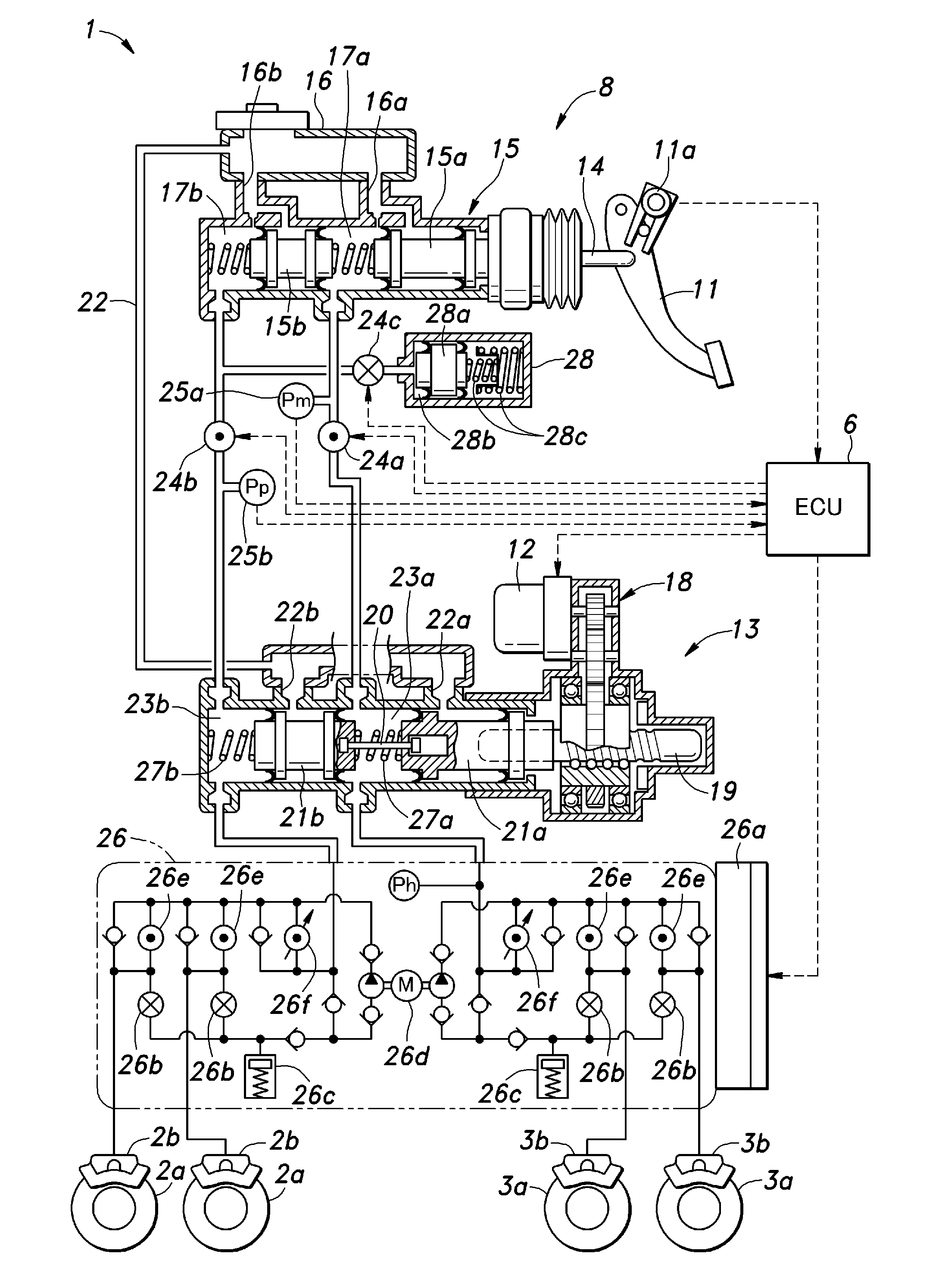
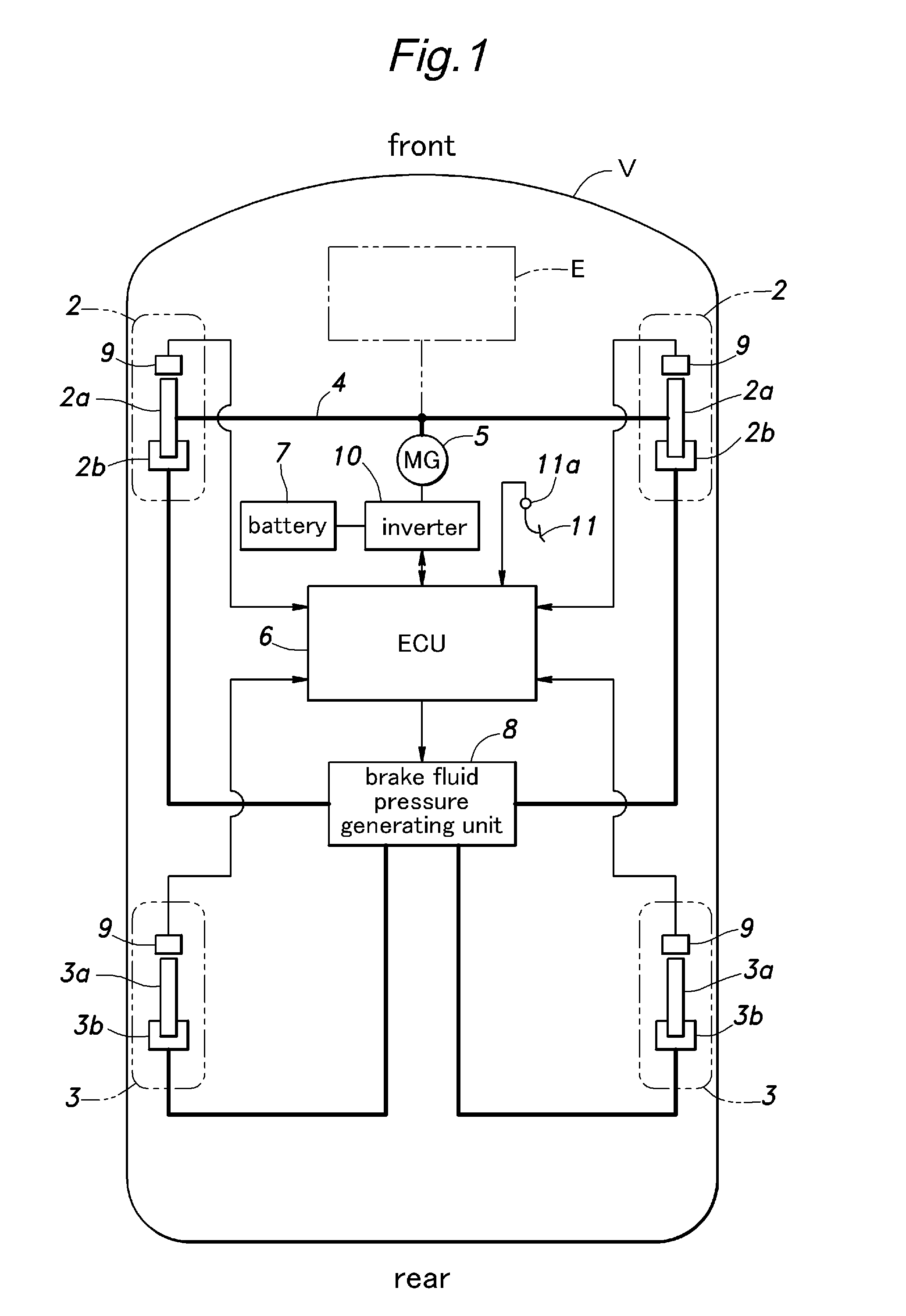
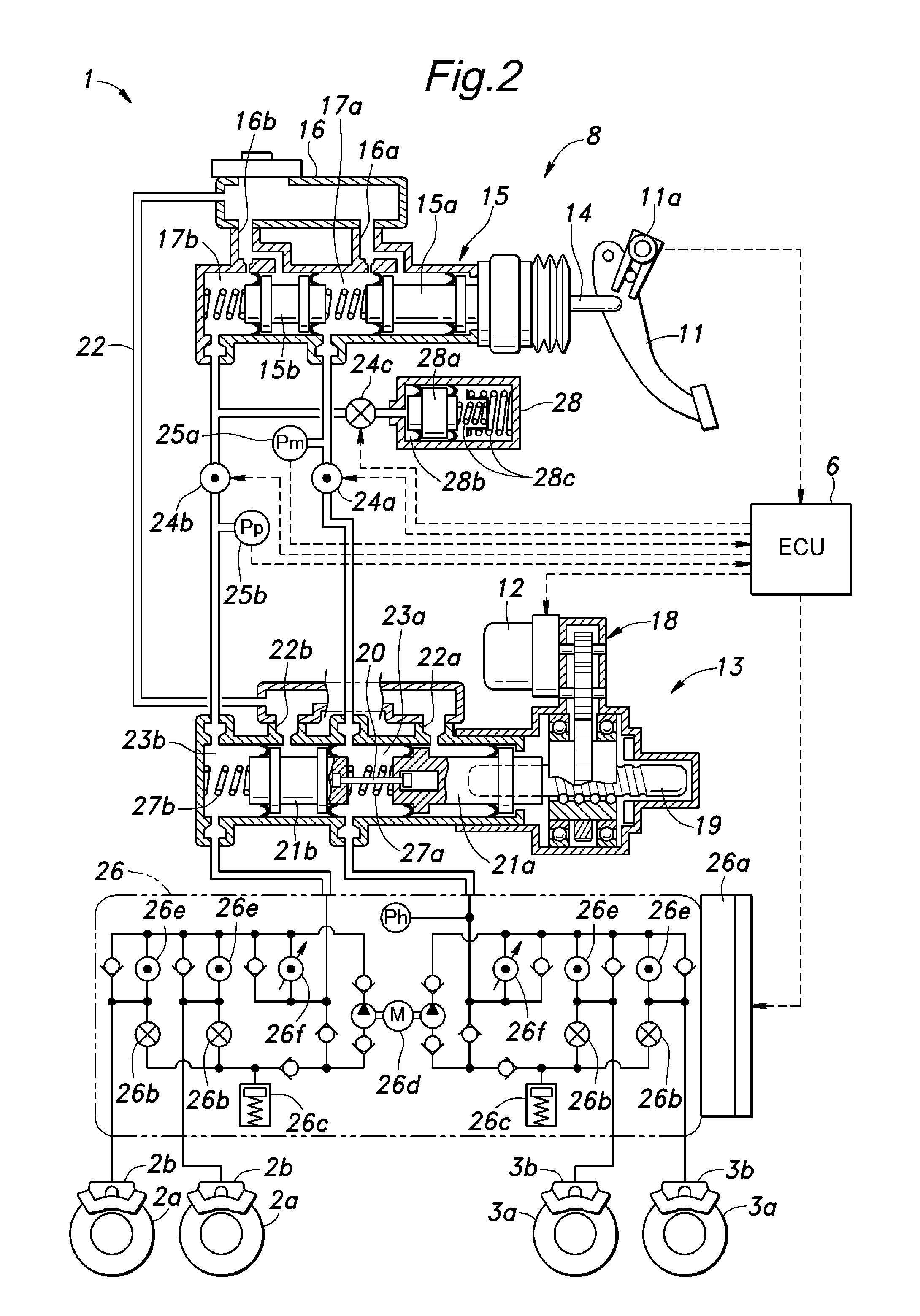
[0026]FIG. 1 shows a brake system of an electric or hybrid vehicle embodying the present invention. This vehicle V comprises a pair of front wheels 2 located on the front side thereof and a pair of rear wheels 3 located on the rear side thereof. The front wheels 2 are connected to front axles 4 which are in turn connected to a motor / generator 5 in a torque transmitting relationship via a differential gear device (not shown in the drawing).

[0027]The motor / generator 5 operates both as an electric motor for propelling the vehicle and a generator for providing a regenerative braking. More specifically, the motor / generator 5 can receive electric power from a rechargeable battery 7 serving as a power source via an inverter 10, and can also supply electric power to (recharge) the battery 7 by converting the kinetic energy into electric power by the regenerative braking.

[0028]A control unit (ECU) 6 incorporated with a CPU control circuit performs various control actions for the vehicle V in...


PUM


Abstract

In a brake-by-wire vehicle brake system using a feedback control unit (12a, 12b, 31, 36, 45) for producing a brake fluid pressure according to a brake input, a response restricting unit (26, 39, 48) restricts a response property of the feedback control unit when an extraneous brake fluid control operation is detected. Thereby, the control unit is prevented from excessively reacting to changes in the brake fluid pressure caused by the extraneous brake fluid control operation, and the vehicle brake system can provide a highly responsive property and a resistance to changes in the brake fluid pressure at the same time.

Description

TECHNICAL FIELD[0001]The present invention relates to a vehicle brake system, and in particular to a vehicle brake system using an electric actuator for producing a brake fluid pressure.BACKGROUND OF THE INVENTION[0002]In electric vehicles and hybrid vehicles, it is a common practice to use the electric motor which is connected to the drive axle of the vehicle as a generator that produces electric power and provides a braking force at the same time when decelerating the vehicle. This is called as regenerative braking. However, the regenerative braking is generally inadequate for providing all of the need for the braking force, and it is common to combine the more conventional hydraulic (friction) braking with the regenerative braking. JP 2008-143256A discloses an electronically controlled brake-by-wire system that controls the hydraulic brake and the regenerative brake in a coordinated manner.[0003]In a brake-by-wire system, a target brake force is set by an input amount given by a ...

Claims


Application Information

Patent Timeline
IPC IPC(8): B60T13/74
CPCB60T7/042B60T8/4081B60T13/745
Inventor NISHIOKA, TAKASHIMATSUSHITA, SATOSHIKOBORI, HIDETOSHIOHKUBO, NAOTO
Owner HONDA MOTOR CO LTD
Why Eureka
Try Eureka