Gas injection apparatus and substrate processing apparatus using same

a technology of gas injection and substrate, which is applied in the direction of coatings, chemical vapor deposition coatings, metallic material coating processes, etc., can solve the problems of inconstant deposition uniformity of thin films, increasing the limits of step coverage, etc., and achieves the effect of size and arrangement density of gas injection holes

Active Publication Date: 2012-06-21
WONIK IPS CO LTD
View PDF16 Cites 34 Cited by
  • Summary
  • Abstract
  • Description
  • Claims
  • Application Information

AI Technical Summary

Benefits of technology

[0017]In the gas injection device and the substrate processing apparatus including the gas injection device according to the above-described embodiments, since the process gas is uniformly diffused over the entire area of the substrate in the gas injection units, the process gas may be uniformly injected over the entire area of the substrate.
[0018]In addition, according to the embodiments, the sizes and the arrangement density of the gas injection holes may be gradually increased toward the peripheral side of the substrate support part when considering the rotation of the substrate support part, and thus, a gas may be uniformly supplied over the entire area of a substrate in an actual process.

Problems solved by technology

In addition, as the sizes of contact holes are reduced, limitations in step coverage are increased more and more.
However, when the substrate surface is saturated with the first source gas, the first source gases over the monoatomic layer are physically adsorbed, but chemically adsorbed, due to non-reactivity between the same ligands.
However, there is a limitation that the substrate process apparatus 9 to which the gas injection device 3 is adopted has inconstant deposition uniformity of the thin film.

Method used


Image

  • Gas injection apparatus and substrate processing apparatus using same
  • Gas injection apparatus and substrate processing apparatus using same
  • Gas injection apparatus and substrate processing apparatus using same

Examples


Embodiment Construction

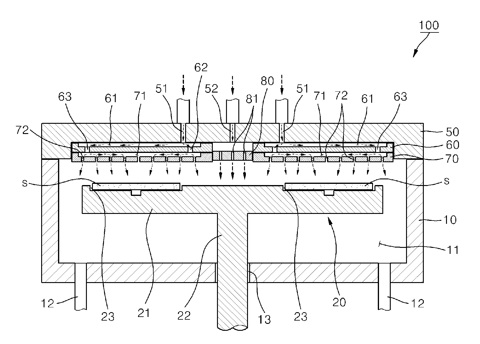
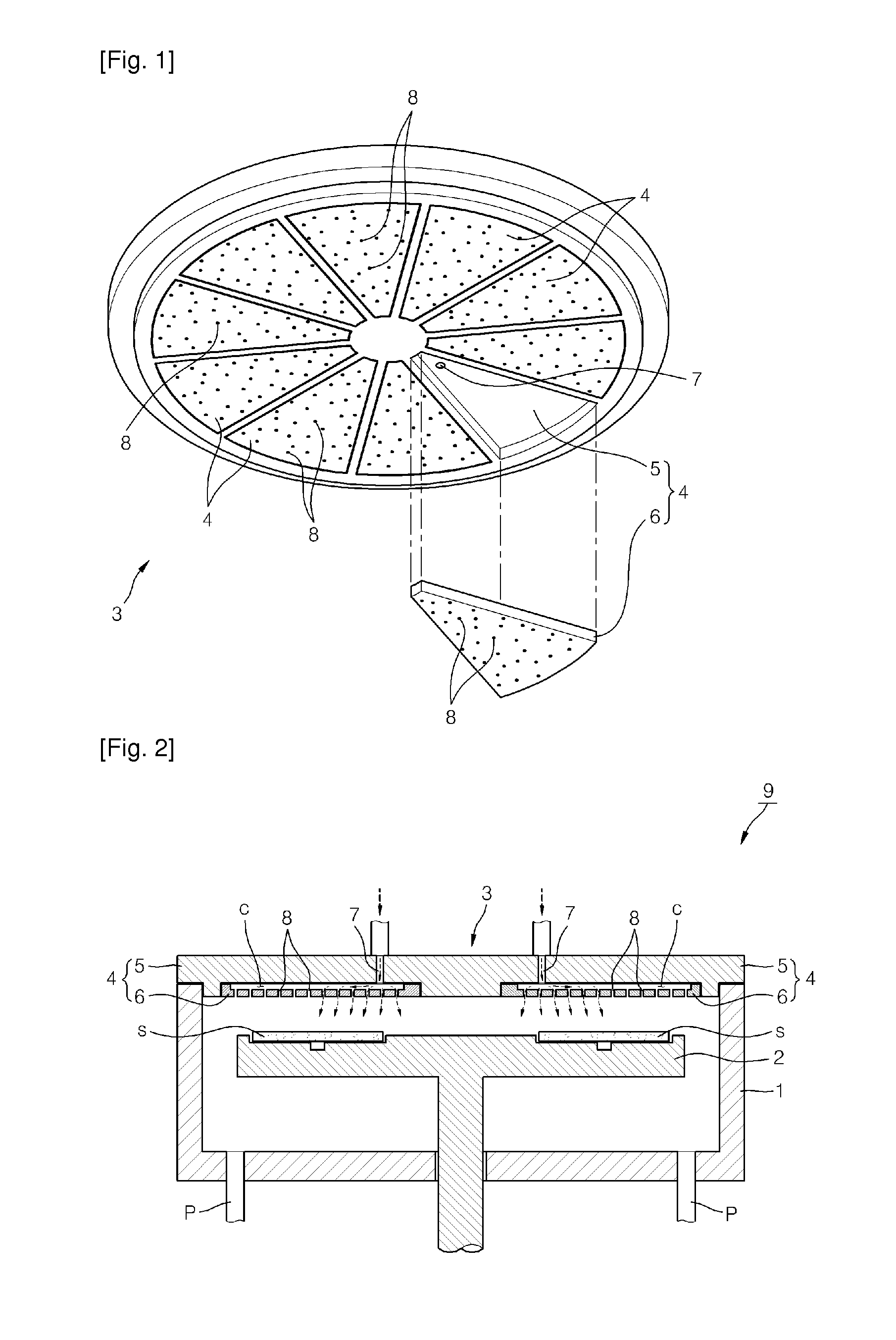
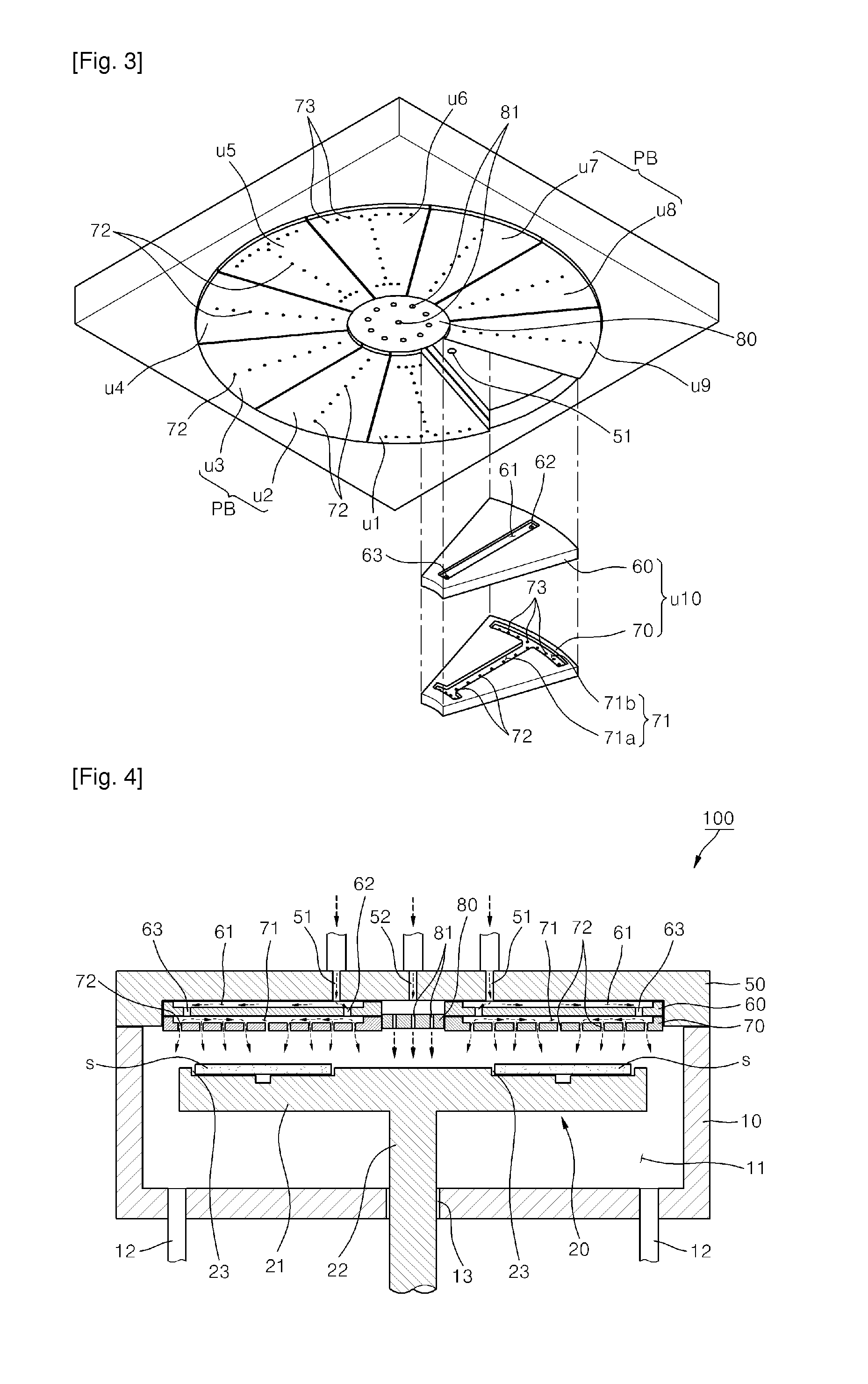
[0026]According to exemplary embodiments, an intermediate plate may be disposed between a top plate and an injection plate. A gas diffusion space may have a first gas diffusion space defined between the top plate and the intermediate plate to communicate with an inlet and a second gas diffusion space defined between the intermediate plate and the injection plate to communicate with a gas injection hole. A plurality of connection holes communicating with the second gas diffusion space may be defined at a lower side of the first gas diffusion space in the intermediate plate.

[0027]Also, according to the exemplary embodiments, the inlet may be provided in plurality along a radius direction of the substrate support part.

[0028]Also, according to the exemplary embodiments, the gas injection holes may have a plurality of first injection holes defined along the radius direction of the substrate support part and a plurality of second injection holes defined along a circumference direction of ...


PUM

PropertyMeasurementUnit
radiusaaaaaaaaaa
diameteraaaaaaaaaa
circumferenceaaaaaaaaaa

Abstract

Provided are a gas injection device and substrate processing apparatus using the same. The gas injection device includes a plurality of gas injection units disposed above a substrate support part rotatably disposed within a chamber to support a plurality of substrates, the plurality of gas injection units being disposed along a circumference direction with respect to a center point of the substrate support part to inject a process gas onto the substrates. Wherein each of the plurality of gas injection units includes a top plate in which an inlet configured to introduce the process gas is provided and an injection plate disposed under the top plate to define a gas diffusion space between the injection plate and the top plate along a radius direction of the substrate support part, the injection plate having a plurality of gas injection holes under the gas diffusion space to inject the process gas introduced through the inlet and diffused in the gas diffusion space onto the substrate. In at least one gas injection unit of the plurality of gas injection units, the process gas is introduced into the gas diffusion space at a plurality of points.

Description

TECHNICAL FIELD[0001]The present disclosure relates to a gas injection device and a substrate processing apparatus using the same, and more particularly, to a substrate processing apparatus in which a plurality of substrates are seated on a substrate support part to perform processes such as thin film deposition and a gas injection device used for the substrate processing apparatus.BACKGROUND ART[0002]As the scales of semiconductor devices gradually decrease, extreme thin films are increasingly required. In addition, as the sizes of contact holes are reduced, limitations in step coverage are increased more and more. Thus, an atomic layer deposition (ALD) method is being used as deposition methods for addressing these limitations. In general, the ALD method is a method in which various source gases are separately supplied to a substrate to form a thin film through surface saturations of the source gases.[0003]The principle of the ALD method will be simply described below. When a firs...

Claims


Application Information

Patent Timeline
Patent Type & Authority Applications(United States)
IPC IPC(8): C23C16/455
CPCC23C16/45551C23C16/45565H01L21/68771H01L21/68764C23C16/45574H01L21/20
Inventor LEE, JUNG-HWANPARK, WOO-YOUNGHAHM, TAE-HO
Owner WONIK IPS CO LTD
Why Eureka
Try Eureka