Electrode for honeycomb structure forming die

a technology of forming die and honeycomb, which is applied in the field of electromechanical devices, can solve the problems of easy breakage of combtooth-like electrodes, abnormal shape of the obtained die, and abnormal shape of the flow-through cells of the obtained honeycomb structure, etc., and achieves the enhancement of strength, high strength, and the effect of increasing the strength of the honeycomb electrode having such a configuration according to the present invention

Active Publication Date: 2012-06-21
NGK INSULATORS LTD
View PDF24 Cites 1 Cited by
  • Summary
  • Abstract
  • Description
  • Claims
  • Application Information

AI Technical Summary

Benefits of technology

[0029]A honeycomb electrode according to the present invention is an electrode for manufacturing a die which forms a honeycomb structure. Therefore, on at least one of two main surfaces of an electrode base body, a plurality of electrode cells partitioned by electrode partition walls should appear, and the shape of the electrode cells is required to be analogous to a shape of flow-through cells of the honeycomb structure. Moreover, a configuration formed by the electrode partition walls and the electrode cells in the honeycomb electrode is schematically similar to part or all of a configuration which appears on an end surface of the honeycomb structure or a section thereof vertical to an axial direction. In the honeycomb electrode according to the present invention, the plurality of electrode cells partitioned by the electrode partition walls appears on only one surface. In other words, the electrode cells do not have to pass through the two main surfaces of the honeycomb electrode (the electrode base body). In the other surface on which any electrode cell does not appear, any opening does not have to be provided, or holes, e.g., round holes connected to the electrode cells may be open. However, in the electrode for the honeycomb structure forming die according to the present invention, the electrode cells do not pass through the two main surfaces.
[0030]The strength of the honeycomb electrode having such a configuration according to the present invention becomes higher as compared with the honeycomb electrode through which the electrode cells pass. That is, in the honeycomb electrode according to the present invention, needless to say, thin electrode partition walls are not formed in the surface on which any electrode cell does not appear, so that the strength is high. For example, about a half or more of a volume of the electrode base body can contribute to the enhancement of the strength. The strength of the electrode becomes high as a whole. Therefore, the electrode partition walls which is formed on a side on which the electrode cells appear, while maintaining a desirable shape, can be made thinner (finer) as compared with an individually independent combtooth-like electrode.
[0031]The electrode for the honeycomb structure forming die according to the present invention is suitable as an electrode for use in obtaining a die including narrower or finer slits for obtaining a honeycomb structure including thinner porous partition walls. As a thickness of each of the electrode partition walls in the electrode for the honeycomb structure forming die according to the present invention, 0.01 mm is realized. In a conventional combtooth-like electrode (see Patent Document 2), a limit of a thickness of each usable flat plate-like projection, i.e., the rib has been 0.03 mm. When widths of slits of dies processed by using the electrodes are compared, the width of each slit of the die processed by the electrode for the honeycomb structure forming die according to the present invention can be 0.03 mm. On the other hand, a limit of the slit width of the die processed by using the conventional combtooth-like electrode (see Patent Document 2) has been 0.05 mm. The slit width of the die is the shortest distance between die substantive parts adjacent via the slit in the die base body.
[

Problems solved by technology

In this case, the breakage of the combtooth-like electrode easily occurs.
For example, if the flat plate-like projections of the combtooth-like electrode break during the electric discharge machining, a shape of the obtained die becomes abnormal.
When the honeycomb structure is formed by using the die having the abnormal shape, a shape of the (flow-through) cells of the obtained honeycomb structure also becomes abnormal, and yield of a cer

Method used


Image

  • Electrode for honeycomb structure forming die
  • Electrode for honeycomb structure forming die
  • Electrode for honeycomb structure forming die

Examples


Embodiment Construction

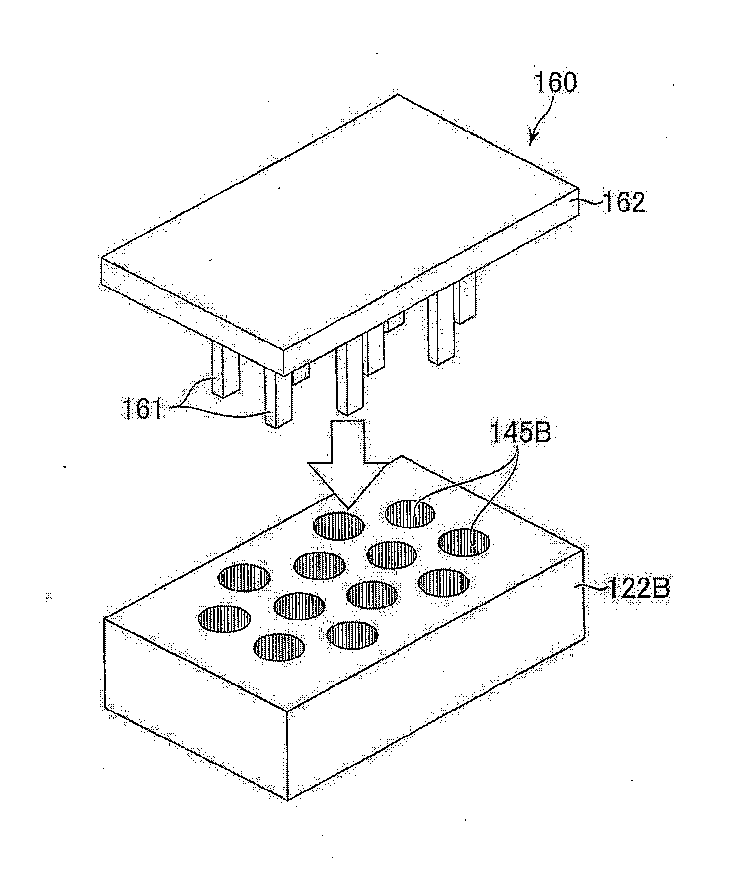
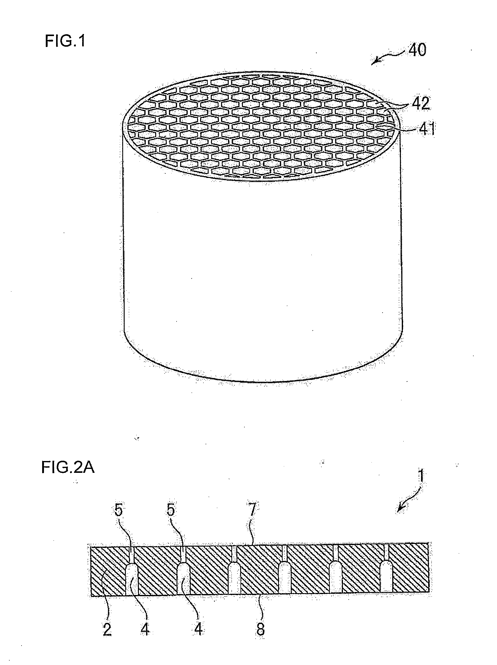
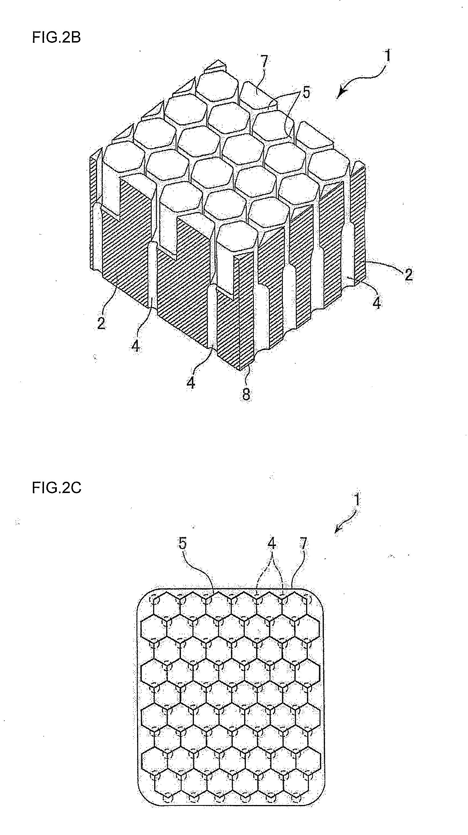
[0057]Hereinafter, embodiments of the present invention will appropriately be described with reference to the drawings, but it should be understood that the present invention is not limited to the following embodiments when interpreted and that various changes, modifications and improvements can be added on the basis of the knowledge of a person skilled in the art, without departing from the scope of the present invention. For example, the drawings show preferable embodiments of the present invention, but the present invention is not limited by configurations or information shown in the drawings. When the present invention is performed or verified, means similar or equivalent to those described in the present description can be applied, but preferable means are described hereinbelow.

[0058]The drawings for use in the following description are schematic views, and in the respective drawings, the number of constituent elements, e.g., electrode cells or electrode partition walls does no...


PUM

PropertyMeasurementUnit
Thicknessaaaaaaaaaa
Thicknessaaaaaaaaaa
Shapeaaaaaaaaaa

Abstract

[Problems] To provide an electrode which enables obtaining a die including thin or narrow slits by electric discharge machining and which does not easily cause breakage or deformation in the die during the electric discharge machining.
[Solution] By providing a honeycomb electrode 120, i.e., an electrode for a honeycomb structure forming die including a thick plate-like electrode base body 122 made of an electricity discharging material and having two main surfaces, only one surface 127 of two main surfaces of the electrode base body 122 is provided with a plurality of electrode cells 142 partitioned by electrode partition walls 141, and a shape of the electrode cells 142 in the one surface 127 is analogous to that of flow-through cells of the honeycomb structure.

Description

TECHNICAL FIELD[0001]The present invention relates to an electrode. The electrode is for use in processing a die. The die is used for forming a honeycomb structure.BACKGROUND ART[0002]A honeycomb structure is usually a ceramic product whose outer shape is a columnar shape or a prism shape. This honeycomb structure includes a plurality of cells partitioned by partition walls being made of a ceramic porous material and having a large number of pores, which has a honeycomb shape. Such a honeycomb structure, including the cells which become through channels of a gas, is often used as a filter or a catalyst carrier.[0003]The honeycomb structure can be manufactured through extrusion forming by use of an extrusion forming machine including a honeycomb structure forming die for exclusive use (also simply referred to as die). This die is obtained by forming, in a die base body made of a pure metal, an alloy or the like, back holes (often referred to as the introduction holes) through which a...

Claims


Application Information

Patent Timeline
IPC IPC(8): B23H1/06
CPCB23H2200/30B23H9/00
Inventor NAGAE, TOMOKIHOSOKAWA, HIROFUMIIWADE, MASANARIHAYASHI, SEIICHIRO
Owner NGK INSULATORS LTD
Why Eureka
Try Eureka