Integrated Air Springs System and Inflatable Air Dam Assembly

a technology of air springs and air dams, which is applied in the direction of roofs, transportation items, loading/unloading vehicle arrangments, etc., can solve the problems of increasing the weight of vehicles, occupying otherwise available space for other vehicular components, and not only costly, so as to reduce the weight of vehicles and reduce the cost , the effect of minimizing duplicity

Inactive Publication Date: 2012-06-21
GM GLOBAL TECH OPERATIONS LLC
View PDF0 Cites 19 Cited by
  • Summary
  • Abstract
  • Description
  • Claims
  • Application Information

AI Technical Summary

Benefits of technology

[0016]The present invention is an integrated pneumatic system for a motor vehicle in which inflatable air dam assembly inflation and deflation is operatively integrated with the air springs system of the motor vehicle, wherein the integration of shared components minimizes duplicity, thereby lowering vehicular weight and cost, while yet providing full functionality of all pneumatic systems of the motor vehicle.
[0017]The integrated pneumatic system according to the present invention includes a motor, air compressor, air dryer, valves (or valving), air lines and electronic controller, and provides pneumatic control over an inflatable air dam assembly and an air springs system, wherein the vehicle trim height adjustment of the air springs may be individual or collective, and wherein the vehicle trim height adjustment of the air springs and the inflation and deflation of the inflatable air dam assembly may be mutually coordinated with respect to vehicular speed and the duration of vehicular speed ranges so as to provide many advantages, including: optimized fuel mileage, improved vehicle ride quality minimized system mass and maximized system efficiency, as well as optimized vehicle road capability, head lamp leveling, etc.
[0018]Accordingly, it is an object of the present invention to provide an integrated pneumatic system for a motor vehicle in which inflatable air dam assembly inflation and deflation is operatively integrated with the air springs system of the motor vehicle, wherein the integration of shared components minimizes duplicity, thereby lowering vehicular weight and cost, while yet providing full functionality of all pneumatic systems of the motor vehicle.

Problems solved by technology

Problematically, the addition of a separate compressor / motor, valves, air dryer, controller, etc, of the deploy / stow system for the inflatable air dam assembly 44 is not only costly, but contributes to increased vehicular weight and occupation of otherwise available space for other vehicular components.

Method used


Image

  • Integrated Air Springs System and Inflatable Air Dam Assembly
  • Integrated Air Springs System and Inflatable Air Dam Assembly
  • Integrated Air Springs System and Inflatable Air Dam Assembly

Examples


Embodiment Construction

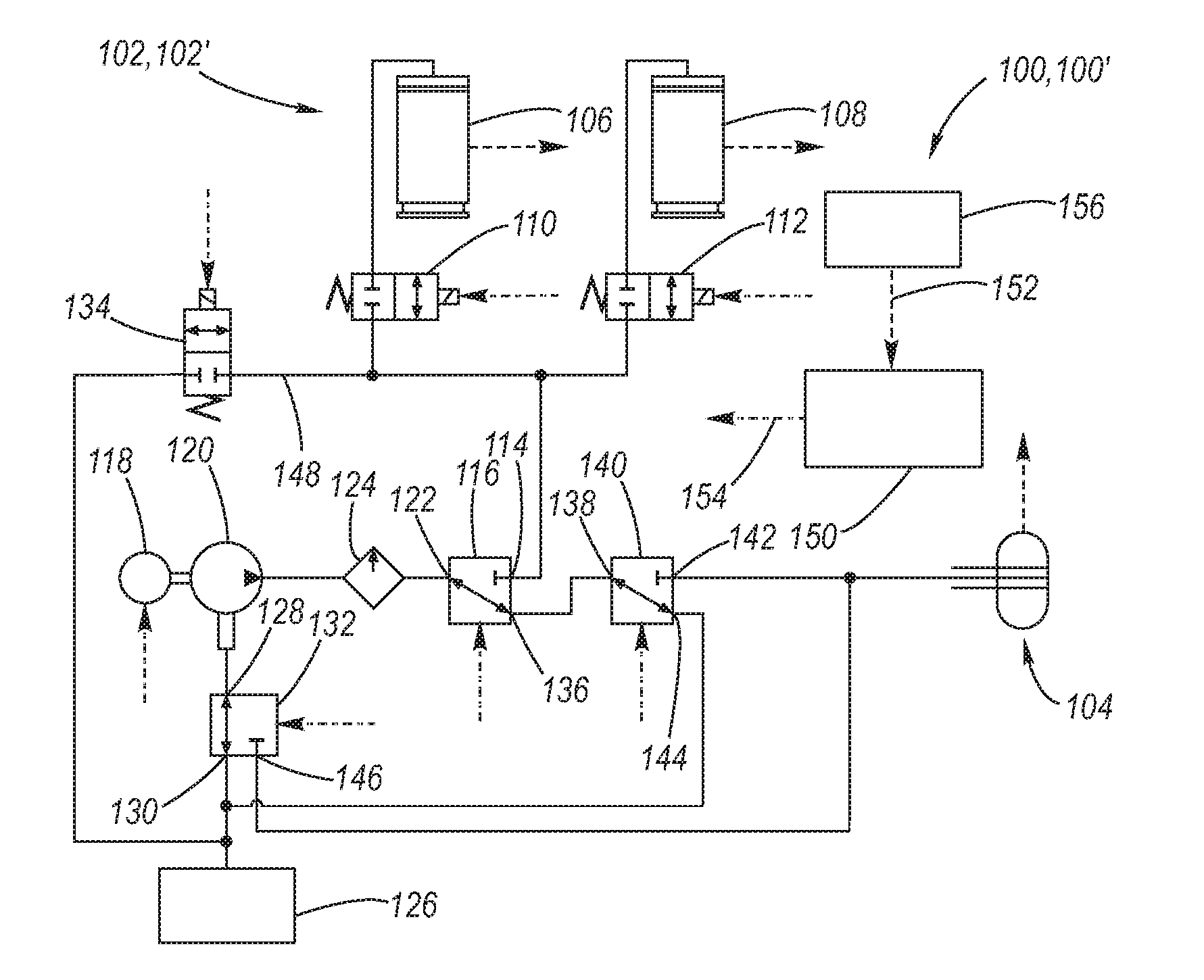
[0029]Referring now to FIGS. 4 through 10, depicted are various aspects of an integrated pneumatic system for a motor vehicle according to the present invention. In this regard, the integrated pneumatic system 100 includes a motor, air compressor, air dryer, valves (or valving), air lines and electronic controller, and provides pneumatic control over an air springs system 102 and an inflatable air dam assembly 104, wherein the trim height adjustment of the air springs and the inflation and deflation of the inflatable air dam assembly may be mutually coordinated with respect to vehicular speed and the duration of vehicular speed ranges so as to provide a number of advantages, including: optimized fuel mileage as well as optimized vehicle road capability and vehicle ride quality.

[0030]Turning attention now to FIGS. 4 through 8, a first example of an integrated pneumatic system 100, 100′ is depicted, wherein the air springs system 102 is a two-corner air springs suspension 102′.

[0031]A...


PUM


Abstract

An integrated pneumatic system including a motor, air compressor, air dryer, valves, air lines and electronic controller pneumatically controls both an air springs system and an inflatable air dam assembly, wherein the trim height adjustment of the air springs may be individual or collective, and wherein the trim height adjustment of the air springs and the inflation and deflation of the inflatable air dam assembly may be mutually coordinated with respect to vehicular speed and the duration of vehicular speed ranges.

Description

TECHNICAL FIELD[0001]The present invention relates generally to motor vehicle air springs systems and inflatable air dam assemblies, and more particularly to an inflatable air dam assembly which is selectively inflated and deflated by integrated operation of the air springs system.BACKGROUND OF THE INVENTION[0002]Motor vehicle air springs systems utilize compressed air operated leveling devices, as for example air springs and / or air spring over shock absorber modules or a combination thereof, to provide ride and leveling control of the vehicle. Such air suspension systems utilize an air compressor to provide a source of compressed air to the air operated leveling devices. In a typical configuration, as for example described in any of U.S. Pat. Nos. 4,829,436, 5,465,209, 6,698,778, and 7,617,031 the air compressor is selectively connected by electronically controlled solenoid valves to the air operated leveling devices, a compressed air reservoir (optional), an air intake, and an air...

Claims


Application Information

Patent Timeline
Patent Type & Authority Applications(United States)
IPC IPC(8): B60G17/016B60G17/015B60G17/052B62D37/02
CPCB62D35/005B60G11/27B60G17/0195B60G2600/02B60G2202/152B60G2400/204B60G2500/30B60G17/0565Y02T10/82
Inventor LI, YUNJUN
Owner GM GLOBAL TECH OPERATIONS LLC
Why Eureka
Try Eureka