Electric Motor Having Electrical Connector Rack

Active Publication Date: 2012-06-21
C & E FEIN
View PDF12 Cites 3 Cited by
  • Summary
  • Abstract
  • Description
  • Claims
  • Application Information

AI Technical Summary

Benefits of technology

[0007]It is a first object of the invention to disclose a connector rack for an electric motor, in particular for an electronically commutab

Problems solved by technology

However, it has been shown that the production and in particular the handling of the grid layers of such stamped grids are particularly complex if a plurality of different contacts are to be configur

Method used


Image

  • Electric Motor Having Electrical Connector Rack
  • Electric Motor Having Electrical Connector Rack
  • Electric Motor Having Electrical Connector Rack

Examples


Embodiment Construction

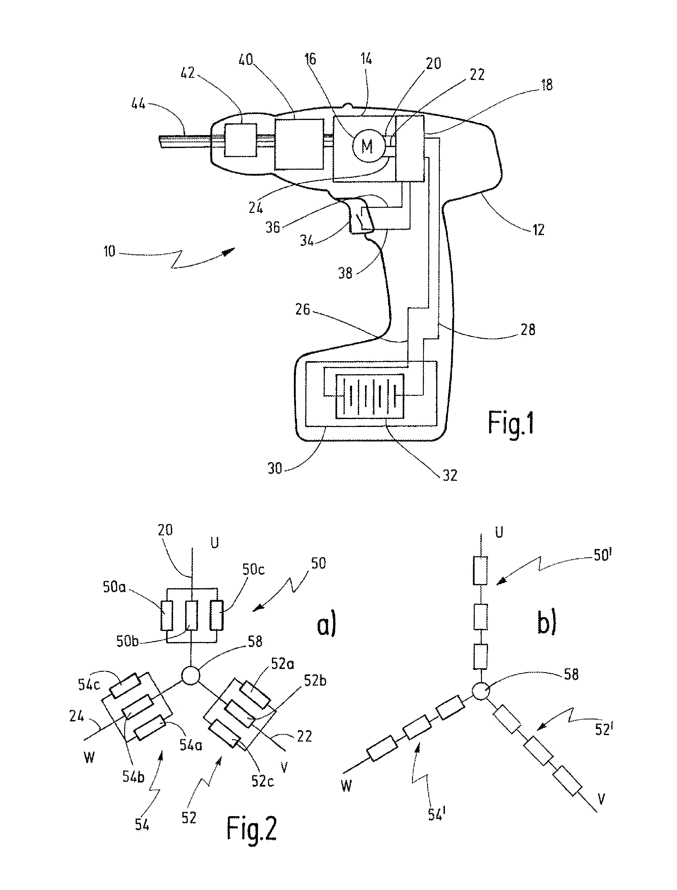
[0062]FIG. 1 schematically shows a power tool, which is identified as a whole by 10.

[0063]The power tool 10 has a housing 12, in which a drive 14 having an electric motor 16 and a motor controller 18 is accommodated. For example, the electric motor 16 has three contacts 20, 22, 24, via which three winding phases U, V, W can be energized, for example. It can thus be an electric motor, to which a rotary field is applied, having a permanently excited rotor, in this case.

[0064]The motor controller 18 is configured for the purpose of applying the alternating field to the phases of the motor U, V, W. This type of excitation can be an electronic commutation. The alternating field can in this case have a sinusoidal curve, can be configured as block shaped, or can have a pulse-width-modulated block-shaped signal curve, by means of which a sinusoidal curve can be approximated, for example.

[0065]The motor controller 18 is coupled via supply lines 26, 28 to a power supply unit 30. According to ...


PUM


Abstract

The invention discloses a connector rack for an electric motor, in particular for an electronically commutable motor having a plurality of exciter windings for a power tool, having at least one electronic mounting board, on which a plurality of contact carriers is provided for electrically contacting the exciter windings.

Description

CROSSREFERENCES TO RELATED APPLICATIONS[0001]This application claims priority from German patent application 10 2010 056 120.7, filed on Dec. 20, 2010. The entire contents of this priority application is incorporated herein by reference.BACKGROUND OF THE INVENTION[0002]The invention relates to a connector rack for an electric motor, in particular for an electronically commutable motor having a plurality of exciter windings for a power tool.[0003]Furthermore, the invention relates to an electric motor having such a connector rack.[0004]Such a connector rack or such an electric motor is known from WO 2002 / 087057 A1.[0005]The known electric motor is an electronically commuted DC motor having a stamped grid, on which plug pins, winding phases, power terminals, and terminals of further components are contacted. The stamped grid has an upper grid layer and a lower grid layer, which each comprise a number of contacts.[0006]A compact construction of the electric motor can be supported using...

Claims


Application Information

Patent Timeline
IPC IPC(8): H02K11/00
CPCH02K2203/03H02K3/522
Inventor MAYER, BERND
Owner C & E FEIN
Why Eureka
Try Eureka