
Method and device for generating electricity and method of fabrication thereof

a technology of generating electricity and manufacturing methods, applied in the direction of vacuum evaporation coating, electric/magnetic element fluid pressure measurement, sputtering coating, etc., can solve the problems of fuel consumption, electrode corrosion, chemical degradation of parts of the device,

Active Publication Date: 2012-06-21
LANDA LABS 2012
View PDF8 Cites 48 Cited by
  • Summary
  • Abstract
  • Description
  • Claims
  • Application Information

AI Technical Summary

Benefits of technology

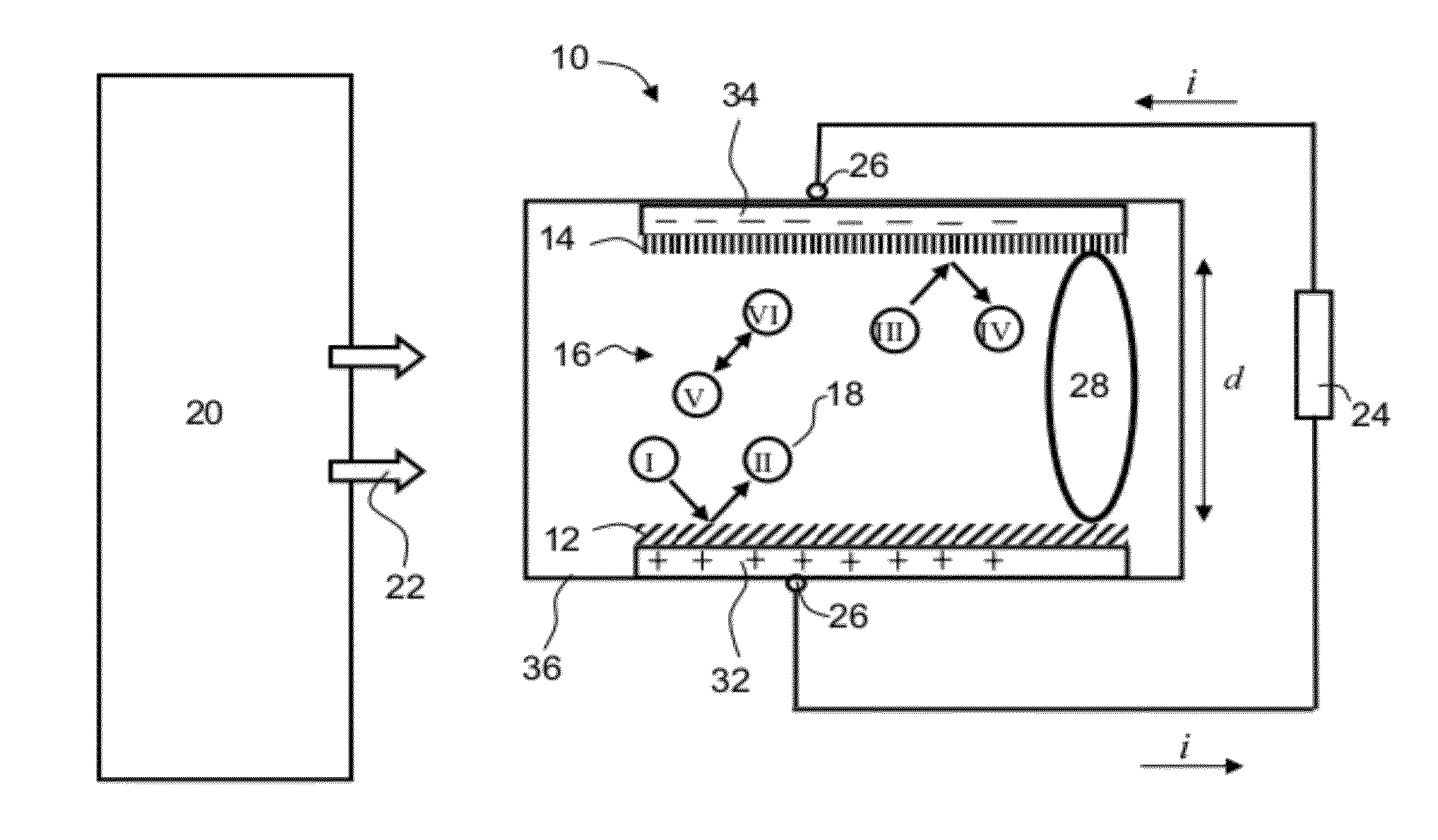
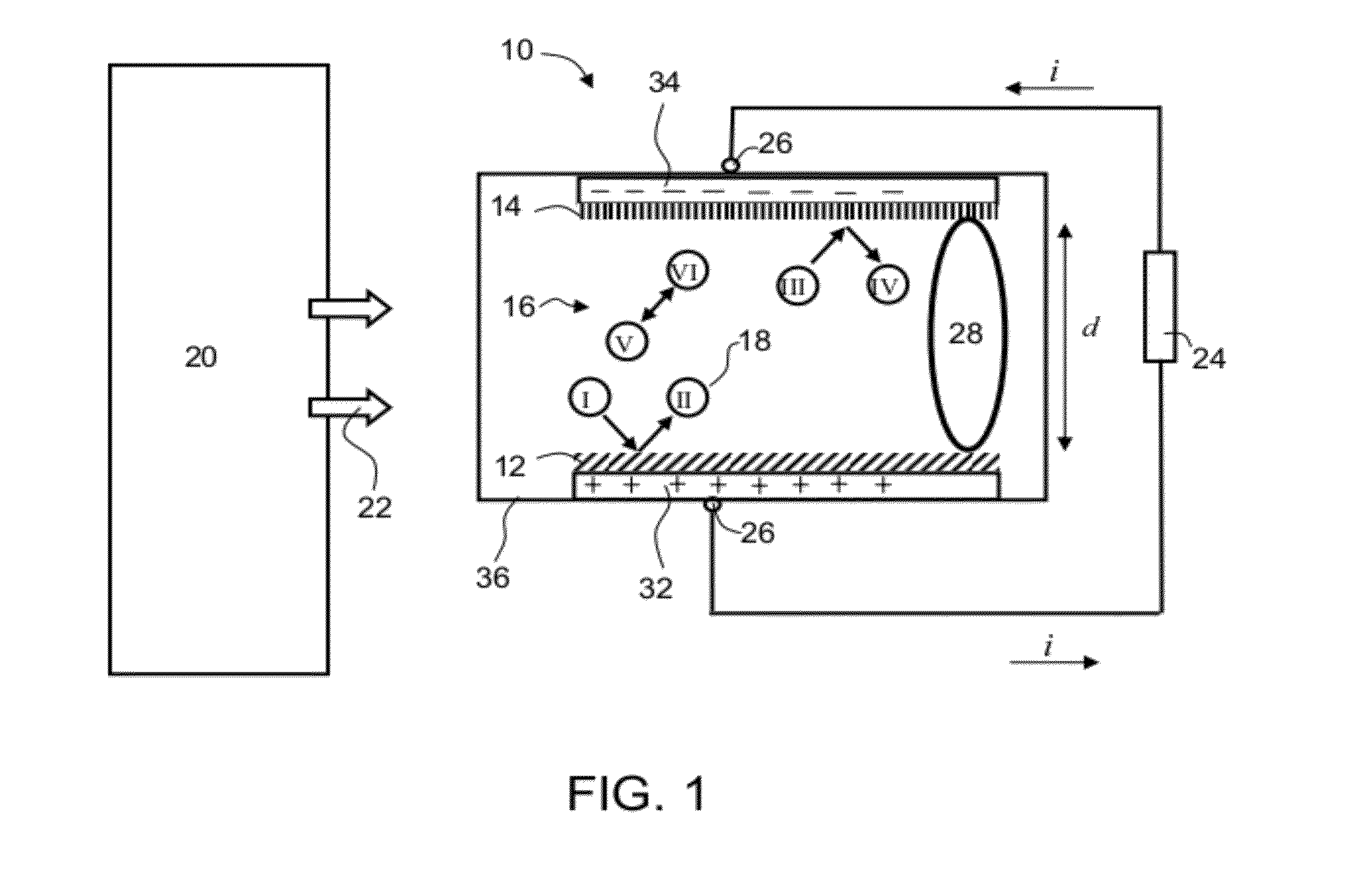
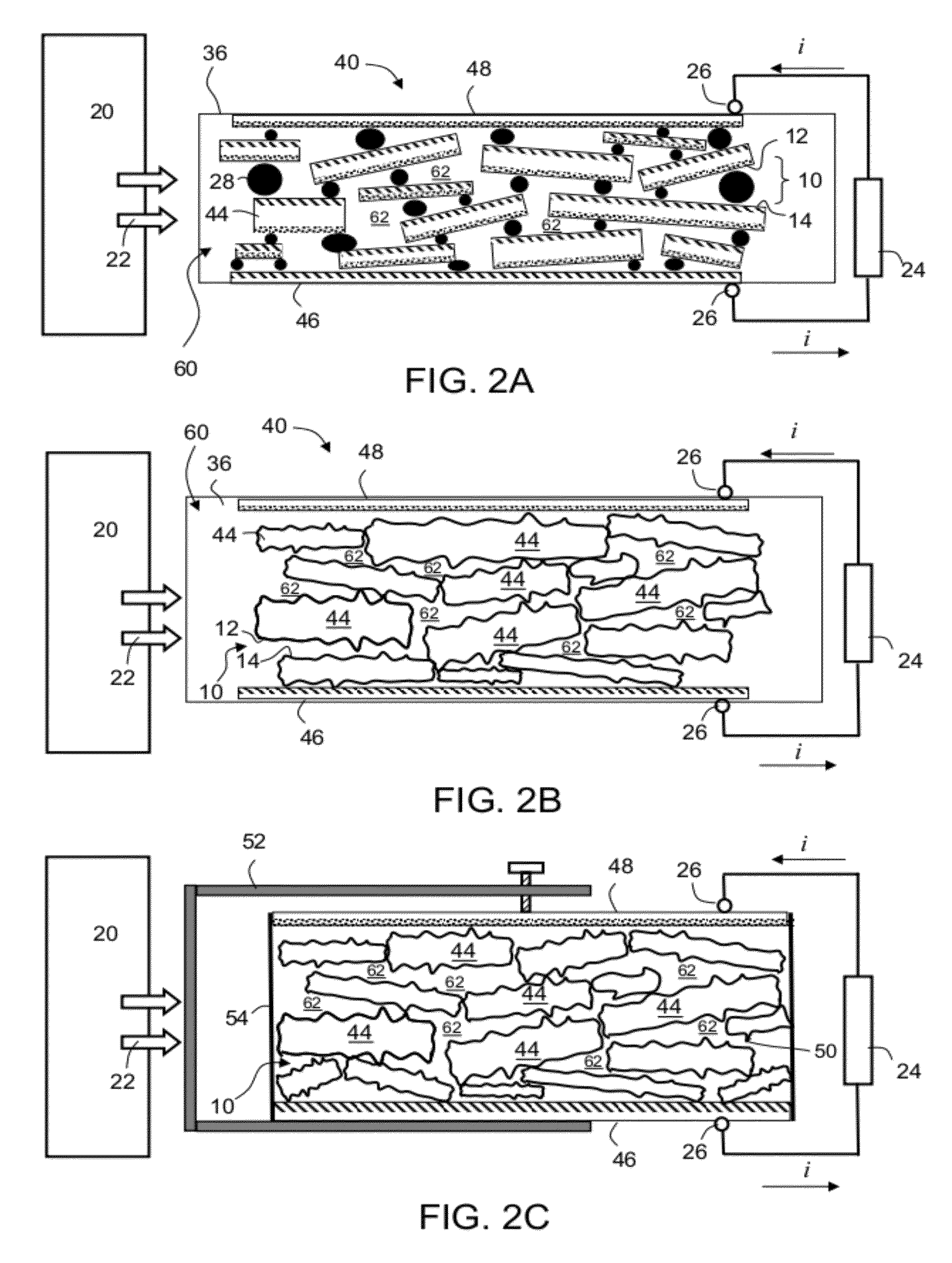
The present invention is about a device that generates electricity by using the thermal motion of gas molecules in a gas medium. The device consists of a structure made up of particles with voids between them. The particles have surfaces that act as active cells, where the gas molecules transfer charge to or from. The charge transferability of the surfaces is different, which allows for the separation of the particles and the use of one surface electrode. The invention also includes methods for modifying the surfaces of the particles to have different charge transferability. The device can be used as an electrical generator using a compatible gas to transfer charge between particles. The invention also includes a method for fabricating the device and a method for modifying the surfaces of the particles.

Problems solved by technology

Closed electrochemical cells, commonly known as batteries, are but one example of such electricity generators, but are generally used for storage rather than meaningful electricity production, since their production is limited by the amount of chemical reactant contained in the battery.
Both the closed and open devices share the principle that an irreversible chemical reaction is taking place between the electrodes and the electrolyte, or within the electrolyte, generally resulting in chemical degradation of parts of the devices, such as corrosion of the electrodes, or consumption of the fuel.

Method used


Image

  • Method and device for generating electricity and method of fabrication thereof
  • Method and device for generating electricity and method of fabrication thereof
  • Method and device for generating electricity and method of fabrication thereof

Examples


examples

[0229]Reference is now made to the following examples, which together with the above descriptions illustrate some embodiments of the invention in a non limiting fashion.

example i

Theoretical Considerations

[0230]The theoretical considerations suggested by the present inventors as hypothetically underlying the generation of electrical current by thermal motion of gas molecules between surfaces having different charge transferability were provided in Example 1 of International Publication No. WO 2010 / 023669 A2, the contents of which are hereby incorporated by reference.

example 2

Measurements by Kelvin Probe

[0231]The present example describes experiments performed in accordance with some embodiments of the present invention to assess the charge transferability of surfaces by means of a Kelvin probe. The experiments were performed as described in Example 3 of International Publication No. WO 2010 / 023669 A2, the contents of which are hereby incorporated by reference, with a minor modification regarding baseline vacuum levels.

[0232]The samples of Table 1A correspond to the experiments disclosed in WO 2010 / 023669 A2, for which the baseline vacuum level was of about 10−2 mbar.

[0233]In additional experiments, the Kelvin probe apparatus (Kelvin Control 07, Besocke Delta Phi) was placed in a sealable chamber allowing vacuum pressure of about 10−3 mbar. The samples were prepared by sputtering of layers of 30-1,000 nm of the desired material on a thin disc or square glass element of 1 mm thickness (for more details see Example 5, TGD and STG supports). Samples of alum...


PUM

PropertyMeasurementUnit
thicknessaaaaaaaaaa
distanceaaaaaaaaaa
distanceaaaaaaaaaa

Abstract

Particulated structures and their method of manufacture for use in an electrical generator employing gas-mediated charge transfer are disclosed. The structures comprise a multiplicity of particles which contain voids between first and second opposing surfaces of said particles. At least a portion of said opposing surfaces are modified such that the charge transferability of said first opposing surfaces differs from the charge transferability of said second opposing surfaces.

Description

RELATED APPLICATIONS[0001]This application claims the benefit of priority from International Patent Application No. PCT / IL2009 / 000831, filed Aug. 27, 2009, and U.S. Application Nos. 61 / 310,188, filed Mar. 3, 2010, and 61 / 310,313, filed Mar. 4, 2010.[0002]The contents of all of the above documents are incorporated by reference as if fully set forth herein.FIELD AND BACKGROUND OF THE INVENTION[0003]The present invention, in some embodiments thereof, relates to energy conversion and, more particularly, but not exclusively, to a device and method for generating electricity. Some embodiments relate to a method suitable for fabricating a structure which can be incorporated in a device for generating electricity.[0004]Energy conversion systems receive energy in one form and convert it to energy in another form. In many cases, mechanical energy, resulting for instance from heat engines, hydro, or wind power, drives the rotation of turbines resulting in the generation of electricity. In othe...

Claims


Application Information

Patent Timeline
Patent Type & Authority Applications(United States)
IPC IPC(8): H02N3/00B05D3/00B32B5/16C25D13/12C25D7/00B05D5/12B05D3/14
CPCH01J45/00H02N11/002H02N3/00Y10T428/249921C25D7/00H02N11/00B05D1/005B05D1/02B05D1/40B28B3/02B28B11/24C23C14/34C25D13/12
Inventor LANDA, BENZIONYAYON, YOSEFABRAMOVICH, SAGIOFIR, ASHERRUBIN BEN-HAIM, NIRLION, AMIR
Owner LANDA LABS 2012
Learn More