
Endoscope objective lens and endoscope using the same

Active Publication Date: 2012-06-21
OLYMPUS CORP
View PDF2 Cites 11 Cited by
  • Summary
  • Abstract
  • Description
  • Claims
  • Application Information

AI Technical Summary

Benefits of technology

[0003]The present invention relates to an endoscope objective lens that has a simple configuration and is suitable for a compact, high-resolution image acquisition device usable in laser treatment and the like, and to an endoscope using the same.

Problems solved by technology

However, because this configuration is asymmetrical with respect to the aperture stop, correcting lateral chromatic aberration is especially difficult.

Method used


Image

  • Endoscope objective lens and endoscope using the same
  • Endoscope objective lens and endoscope using the same
  • Endoscope objective lens and endoscope using the same

Examples


example 1

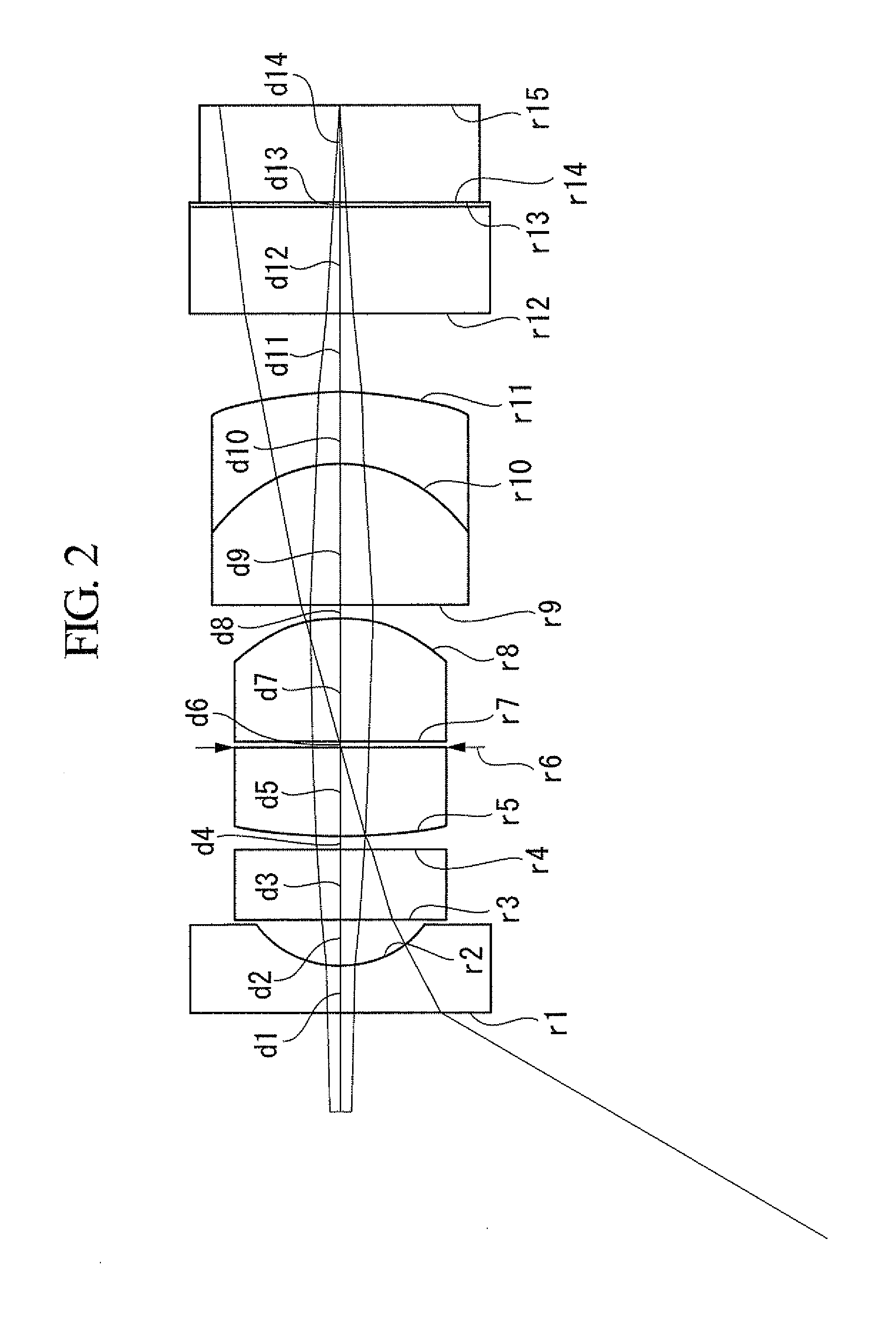
[0051]FIG. 2 shows the configuration of an endoscope objective lens according to Example 1, and the lens data thereof are shown below. FIG. 3 shows aberration diagrams of the objective lens according to this example.

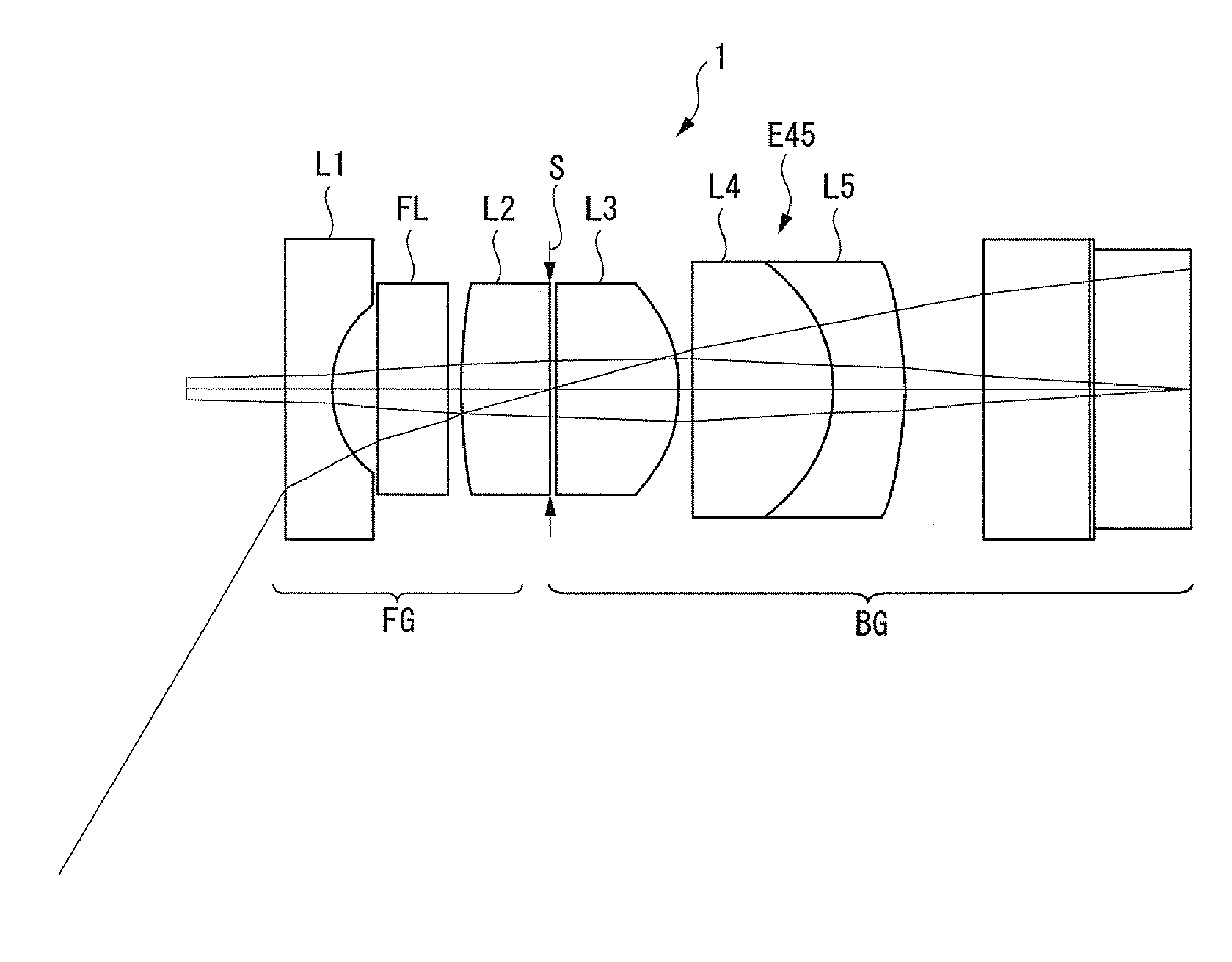
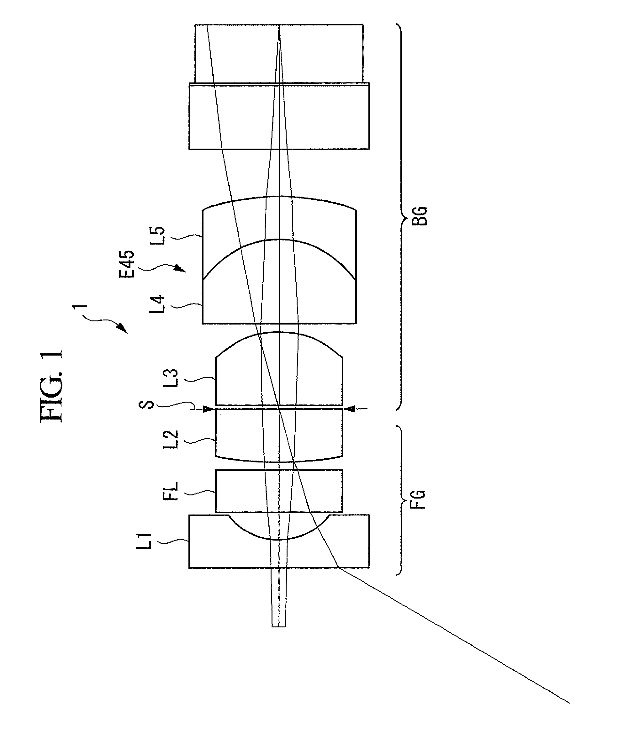
[0052]The endoscope objective lens according to this example is formed of, in sequence from the object side, a front group, an aperture stop, and a back group. The front group is formed of, in sequence from the object side, a negative first lens whose concave surface faces the image side, a filter, and a positive second lens whose convex surface faces the object side and whose flat surface is located on the image side. The back group is formed of, in sequence from the object side, a positive third lens whose convex surface faces the image side, and a combined lens formed of a plano-convex lens and a negative meniscus lens.

Lens DataSurface NumberrdndνOBJ∞10.34271.0001∞0.36291.76871.792  0.85350.33861.0003∞0.54441.51875.004∞0.10891.0005  3.87380.68581.75035.33  6(S)∞0.0544...

example 2

[0053]FIG. 4 shows the configuration of an endoscope objective lens according to Example 2, and the lens data thereof are shown below. FIG. 5 shows aberration diagrams of the endoscope objective lens according to this example.

[0054]The endoscope objective lens according to this example has the same configuration as the endoscope objective lens according to Example 1.

Lens DataSurface NumberrdndνOBJ∞10.34371.00001∞0.36291.771071.792  0.86880.34621.00003∞0.54441.520075.004∞0.10891.00005  4.03280.68241.755035.33  6(S)∞0.05441.00007∞0.95291.683062.008−1.11870.09071.00009∞1.08931.732054.6810 −1.20890.54441.934018.9011 −3.19750.61701.000012 ∞0.81661.518064.1413 ∞0.03631.512064.0514 ∞0.72591.614050.4915 ∞0.00001.0000IMG∞0.0000

example 3

[0055]FIG. 6 shows the configuration of an endoscope objective lens according to Example 3, and the lens data thereof are shown below. FIG. 7 shows aberration diagrams of the endoscope objective lens according to this example.

[0056]The endoscope objective lens according to this example has the same configuration as the endoscope objective lens according to Example 1.

Lens DataSurface NumberrdndνOBJ∞10.33621.00001∞0.36271.771071.792  0.84360.34451.00003∞0.54401.520075.004∞0.10881.00005  4.21760.67811.755035.33  6(S)∞0.05441.00007∞0.92131.744048.008−1.19260.09071.00009∞1.13881.732054.6810 −1.15080.54401.934018.9011 −3.19520.61651.000012 ∞0.81601.518064.1413 ∞0.03631.512064.0514 ∞0.72531.614050.4915 ∞0.00001.0000IMG∞0.0000


PUM


Abstract

An endoscope objective lens includes, in sequence from an object side, a front group which includes a negative first lens having a concave surface faces at image side, a filter, and a positive second lens having a convex surface at the object side and a flat surface or concave surface at the image side; an aperture stop; and a back group which includes a positive third lens having a convex surface at the image side, and a combined lens formed of a plano-convex lens or a biconvex lens and a negative meniscus lens, and satisfies the Conditional Expression (1) and (2):n3>−v3 / 12+5.5,  (1)2.0>df / Ih>1.5.  (2)

Description

CROSS-REFERENCE TO RELATED APPLICATIONS[0001]This is a continuation of International Application PCT / JP2010 / 072245, with an international filing date of Dec. 10, 2010, which is hereby incorporated by reference herein in its entirety. This application claims the benefit of Japanese Patent Application No. 2009-292371, the content of which is incorporated herein by reference.BACKGROUND OF THE INVENTION[0002]1. Field of the Invention[0003]The present invention relates to an endoscope objective lens that has a simple configuration and is suitable for a compact, high-resolution image acquisition device usable in laser treatment and the like, and to an endoscope using the same.[0004]2. Description of Related Art[0005]In endoscopes used in the medical field etc., in order to improve the operability and reduce stress on patients, it has been necessary to reduce the diameter of endoscope insertion portions and to reduce the length of rigid portions at the tip. Therefore, objective lenses inst...

Claims


Application Information

Patent Timeline
IPC IPC(8): G02B9/34
CPCA61B1/00096G02B23/243A61B1/00188A61B1/00186
Inventor KATAHIRA, YUKO
Owner OLYMPUS CORP
Learn More