
Controller and controlling method for power converter

Inactive Publication Date: 2012-06-21
RICHTEK TECH
View PDF3 Cites 33 Cited by
  • Summary
  • Abstract
  • Description
  • Claims
  • Application Information

AI Technical Summary

Benefits of technology

[0005]The present invention is further directed to a controlling method for a power converter, which can provide an effective mechanism for output power limit.

Problems solved by technology

In the power converter application, every external component has its maximum allowable current, voltage and power rating, and therefore the output power limit is required for protecting all components in safe operation region.

Method used


Image

  • Controller and controlling method for power converter
  • Controller and controlling method for power converter
  • Controller and controlling method for power converter

Examples


Embodiment Construction

[0025]The present invention will now be described more specifically with reference to the following embodiments. It is to be noted that the following descriptions of preferred embodiments of this invention are presented herein for purpose of illustration and description only. It is not intended to be exhaustive or to be limited to the precise form disclosed.

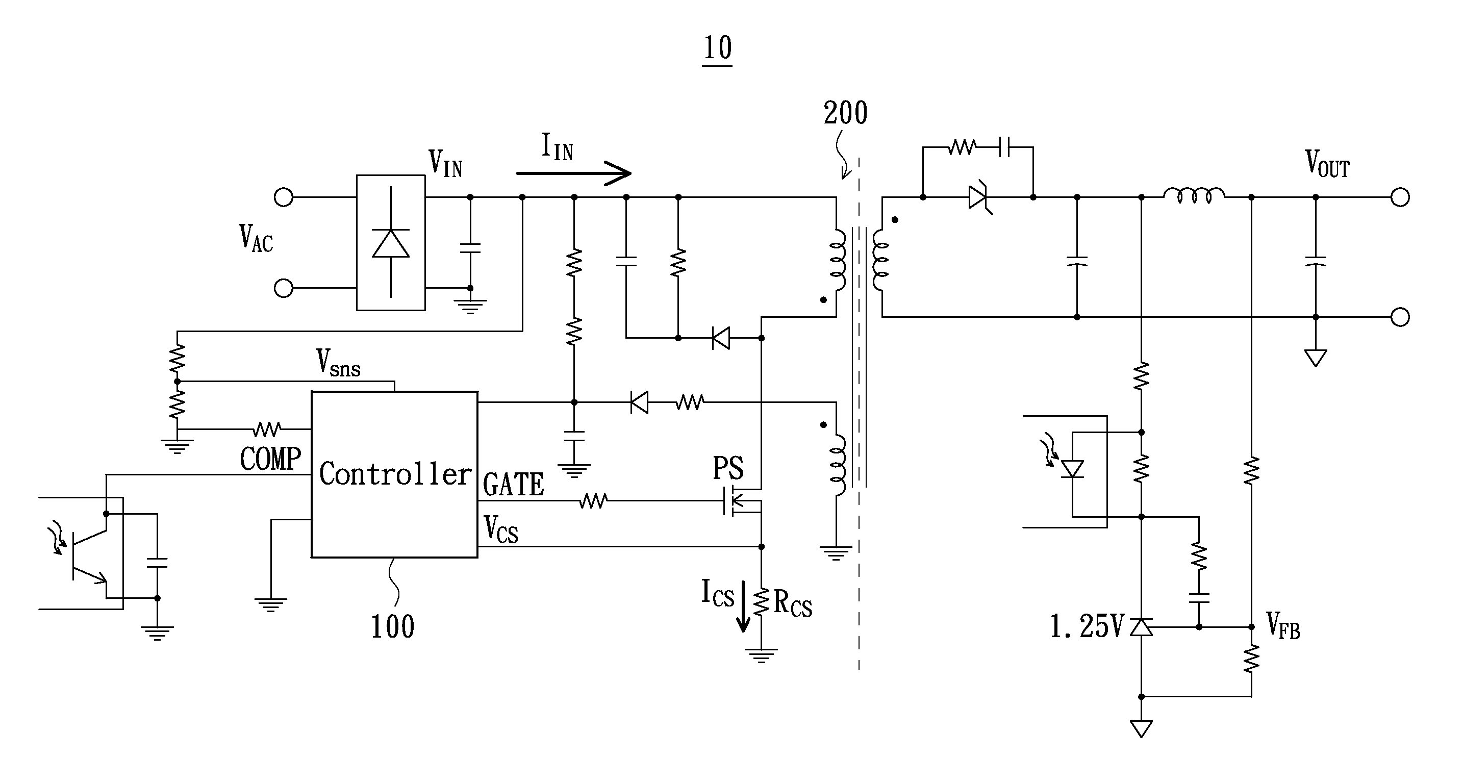
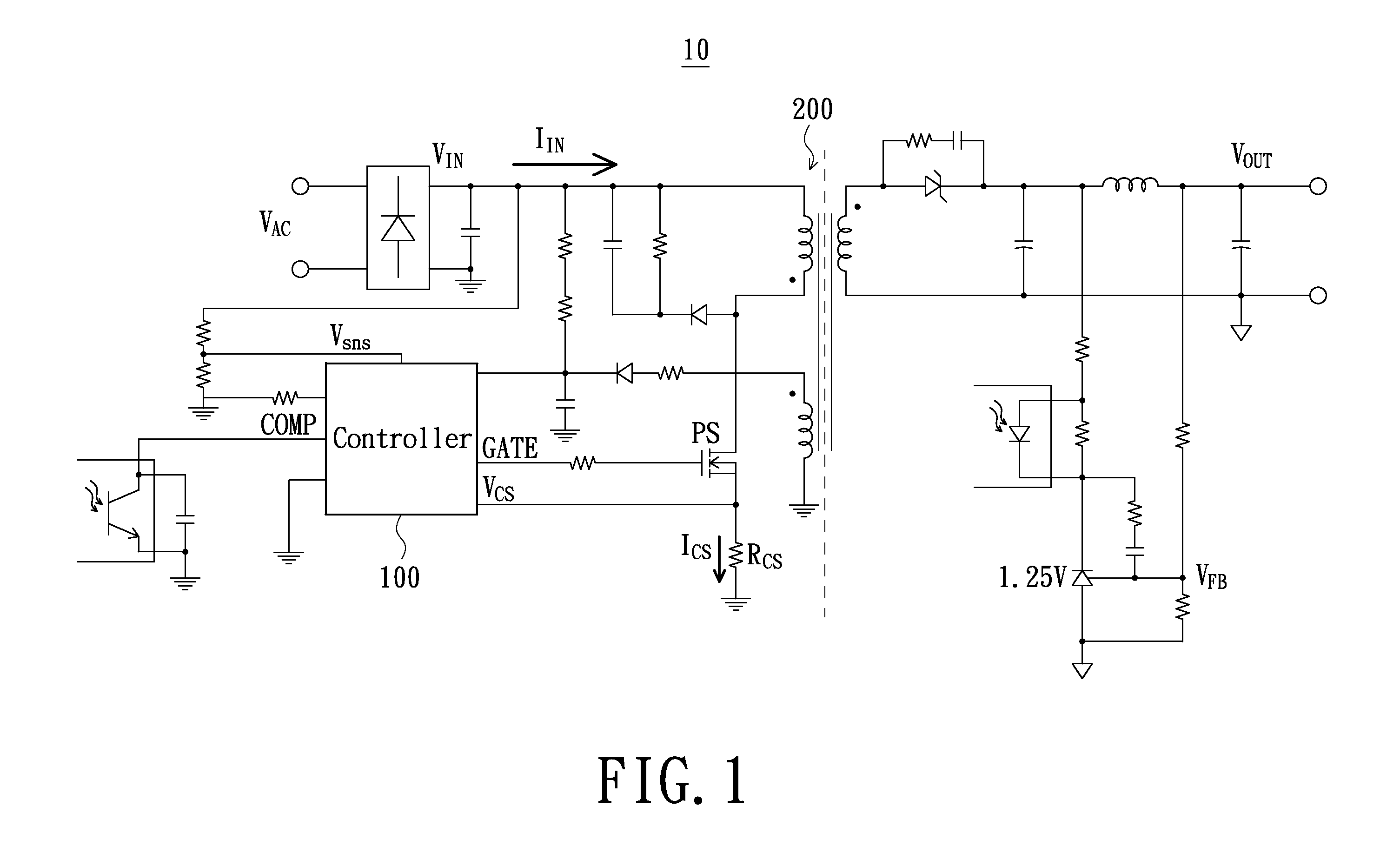
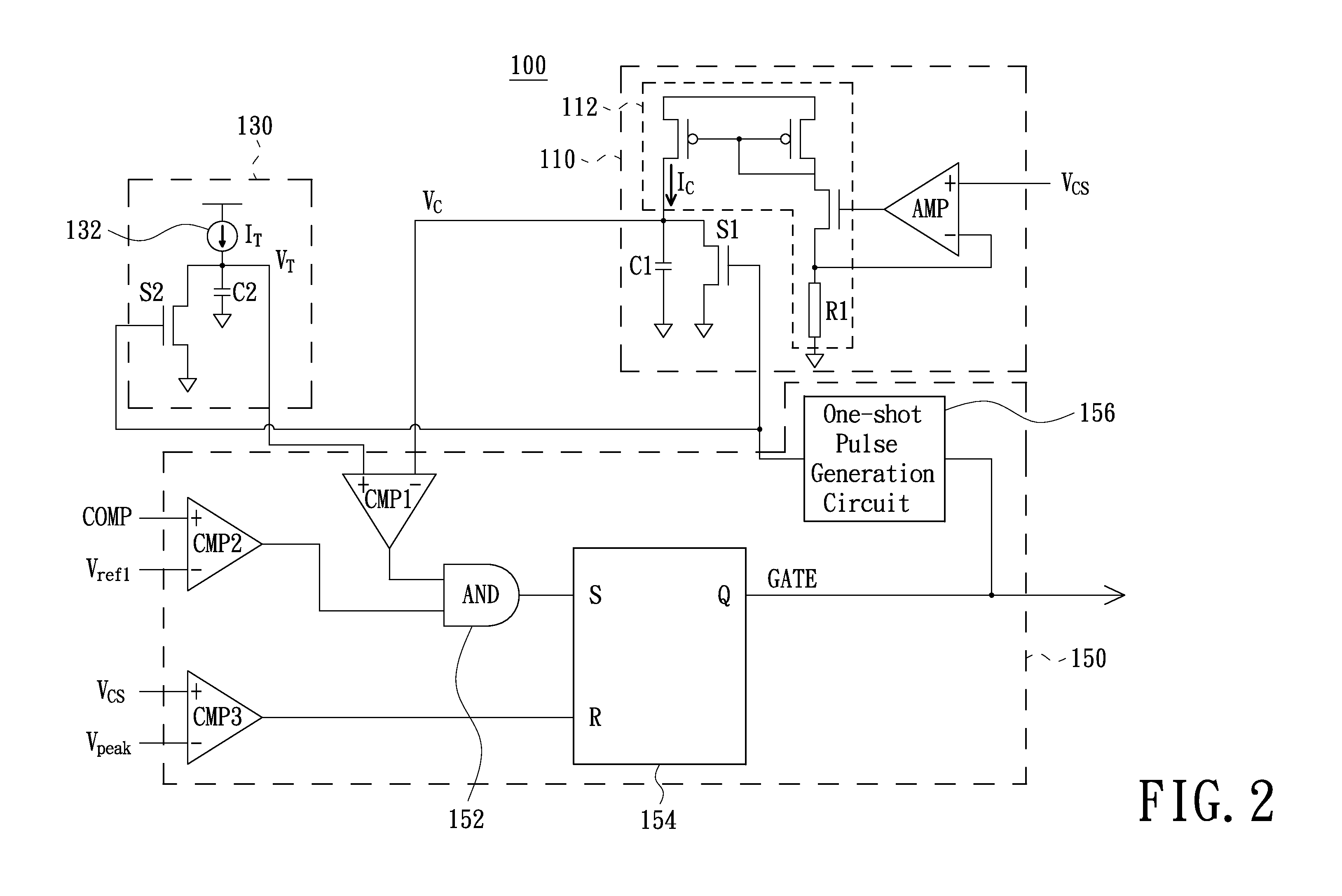
[0026]Referring to FIG. 1, a schematic circuit structure of a power converter to which a controller in accordance with an embodiment of the present invention is applied. As illustrated in FIG. 1, the power converter 10 receives an alternating current (AC) voltage VAC and transforms the received alternating current voltage VAC into a direct current (DC) input voltage VIN by rectifying and filtering, and then uses an energy transfer element 200 e.g., a transformer to transform the direct current input voltage VIN into a direct current output voltage VOUT for supplying power to a load. In particular, the input side of the energy tra...


PUM


Abstract

A controller for a power converter is provided. The controller includes a sense current integrating circuit, a reference current integrating circuit and a drive signal generation circuit. The sense current integrating circuit performs an integrating operation to a sense current representative of a conduction current flowing through a power switch of the power converter and thereby outputs a first integrating result. The reference current integrating circuit performs another integrating operation to a reference current and thereby outputs a second integrating result. The drive signal generation circuit determines a switching period of the power switch according to a status of an output voltage of the power converter cooperative with a relative magnitude relationship between the first integrating result and the second integrating circuit. Furthermore, a controlling method for such power converter also is provided.

Description

FIELD OF THE INVENTION[0001]The present invention relates to power converters, and more particularly to a controller and a controlling method for a power converter.BACKGROUND OF THE INVENTION[0002]Many electrical devices such as cell phones, personal digital assistants (PDAs), laptops, etc. are powered by a source of relatively low-voltage DC power. Because power is generally delivered through a wall outlet as high-voltage AC power, a device, typically referred to as a power converter, is required to transform the high-voltage AC power to a low-voltage DC power, so as to provide output voltages and currents that meet the requirements of the electrical devices.[0003]In operation, a power converter may use a controller to regulate output power delivered to the electrical device (i.e., load), and the power is regulated generally by controlling the ON and OFF states of a power switch in the power converter through the controller. In the power converter application, every external compon...

Claims


Application Information

Patent Timeline
IPC IPC(8): H02M3/335
CPCH02M2001/0009H02M3/33507H02M1/0009
Inventor TANG, CHIEN-FUCHEN, ISAAC Y.PAN, JIUN-HUNG
Owner RICHTEK TECH
Learn More