
Overhead Reduction for Multi-Carrier Transmission Systems

a transmission system and multi-carrier technology, applied in the direction of transmission path division, signalling characterisation, wireless commuication services, etc., can solve the problems of large amount of transmission overhead, outage situation, and further increase of overhead, and achieve good cell-edge performance

Inactive Publication Date: 2012-06-21
NOKIA SOLUTIONS & NETWORKS OY
View PDF5 Cites 20 Cited by
  • Summary
  • Abstract
  • Description
  • Claims
  • Application Information

AI Technical Summary

Benefits of technology

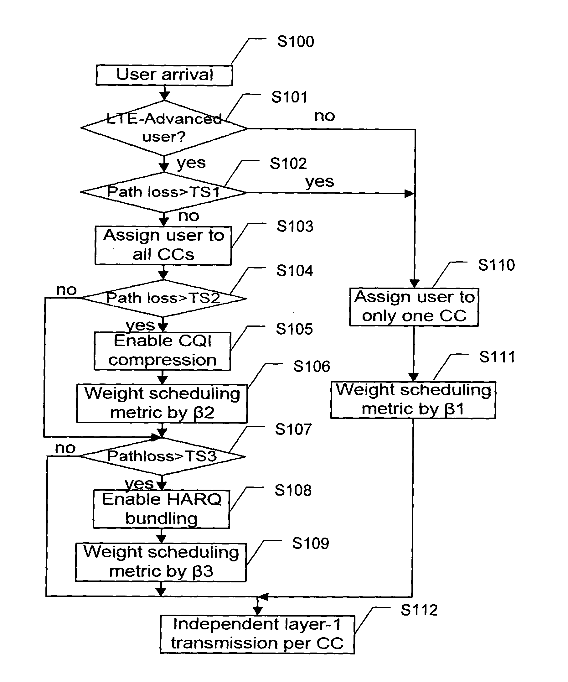
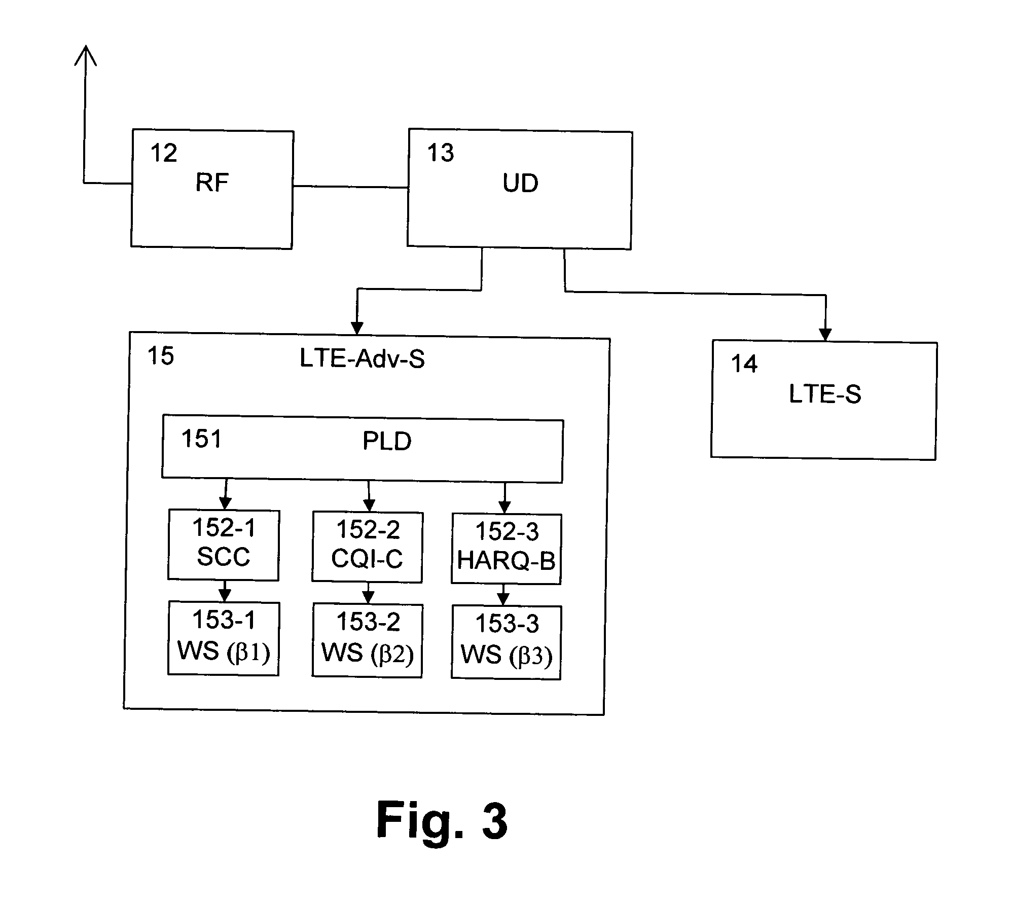
[0012]Accordingly, it is individually and adaptively decided per user and corresponding channel quality which feedback overhead reduction technique to use. Thereby, performance in multi-carrier systems in one transmission direction can be improved and feedback overhead in the other transmission direction can be limited.
[0017]Additionally, a weight applied to a scheduling metric used for the user may be individually selected based on the result of the channel categorization. Thereby, packet scheduling can be modified to guarantee fairness and good cell-edge performance.

Problems solved by technology

However, such uplink signaling may contribute to a large amount of transmission overhead.
Moreover, when multiple-input multiple-output (MIMO) transmission is used, the overhead is further increased because of the requirement for signaling additional control information (e.g. a Precoding Matrix Indicator (PMI) and / or a Rank Indication (RI).
In addition to inefficiency caused by heave uplink overhead, some cell-edge users that are power limited cannot support the uplink transmission over multiple CCs and will thus be in an outage situation.
A problem is basically how to achieve better downlink performance for a multi-carrier system, while still trying to limit the uplink feedback overhead from CQI and Ack / Nack's.
Thereby, performance in multi-carrier systems in one transmission direction can be improved and feedback overhead in the other transmission direction can be limited.

Method used


Image

  • Overhead Reduction for Multi-Carrier Transmission Systems
  • Overhead Reduction for Multi-Carrier Transmission Systems
  • Overhead Reduction for Multi-Carrier Transmission Systems

Examples


Embodiment Construction

[0027]Exemplary embodiments of the present invention will now be described. Indeed, the invention may be embodied in many different forms and should not be constructed as limited to the embodiments set forth herein. Rather, these embodiments are provided so that this disclosure will satisfy applicable legal requirements. Although the specification may refer to “an”, “one”, or “some” embodiment(s) in several locations, this does not necessarily mean that each such reference is to the same embodiment(s), or that the feature only applies to a single embodiment. Single features of different embodiments may also be combined to provide other embodiments. Like reference numerals refer to like elements throughout.

[0028]The present invention is applicable to any base station device, access device, server device, corresponding component, and / or to any communication system or any combination of different communication systems that support component carriers or multiple carriers. The communicat...


PUM


Abstract

A method, apparatus, and computer program product, wherein a channel quality information received from a user in a multi-carrier transmission system is categorizing on a per-user basis, and one of a plurality of feedback overhead reduction techniques is individually selected for the user in response to a result of the channel categorization.

Description

FIELD OF THE INVENTION[0001]The present invention relates to a method, apparatus, and computer program product for scheduling transmission in a multi-carrier transmission system, such as an OFDM (Orthogonal Frequency Division Multiplexing) based transmission system (e.g. wireless local area network (WLAN), Worldwide Interoperability for Microwave Access (WiMAX), and 3.9 G / Long Term Evolution (LTE)).BACKGROUND OF THE INVENTION[0002]The capacity for wireless communication systems has gone through dramatic increase during the last few years, and it is foreseen that this growth will continue in the future. In order to meet the increasing capacity requirement for the next generation systems, as specified by International Telecommunications Union-Radio Communication Sector (ITU-R), the 3rd Generation Partnership Project (3GPP) is now evolving the current Long Term Evolution (LTE) system towards the advanced version, the so called “LTE-Advanced”.[0003]LTE-Advanced requires a bandwidth of u...

Claims


Application Information

Patent Timeline
IPC IPC(8): H04W72/08
CPCH04L1/0026H04L1/0029H04W28/06H04L1/1825H04L5/0007H04L1/1812
Inventor PEDERSEN, KLAUS INGEMANNWANG, YUANYE
Owner NOKIA SOLUTIONS & NETWORKS OY
Learn More