On IP fragmentation in gtp tunnel

Active Publication Date: 2012-06-21
TELEFON AB LM ERICSSON (PUBL)
View PDF6 Cites 22 Cited by
  • Summary
  • Abstract
  • Description
  • Claims
  • Application Information

AI Technical Summary

Benefits of technology

[0017]The main advantage with the present invention is that fragmentation handling time is reduced due to the less number of fragmentation operations performed. If the tunneled IP fragmentation is performed at the entry of the 1st tunnel, i.e., by eNodeB or P-GW, in the lef

Problems solved by technology

Obviously, it can be seen that too many fragmentation plus reassembly are involved in the GTP tunnel transmission path.
As a result, the performance is impacted badly.
Besides, when there is large number of fragments in the network,

Method used


Image

  • On IP fragmentation in gtp tunnel
  • On IP fragmentation in gtp tunnel
  • On IP fragmentation in gtp tunnel

Examples


Embodiment Construction

[0024]The present invention relates to a method for improving IP fragmentation and transmission of user payload between a User Equipment, UE, and a Peer Node, PN. The payload is transmitted through a transmission path enabled by at least a first and a second established tunnel, said tunnels connecting a first and a second node in a Packet Core Network, PCN. A person skilled in the art would realize that a first node and a PCN, adapted to perform said method described below are also disclosed in the following. The PCN will not be described in any further detail in the present invention.

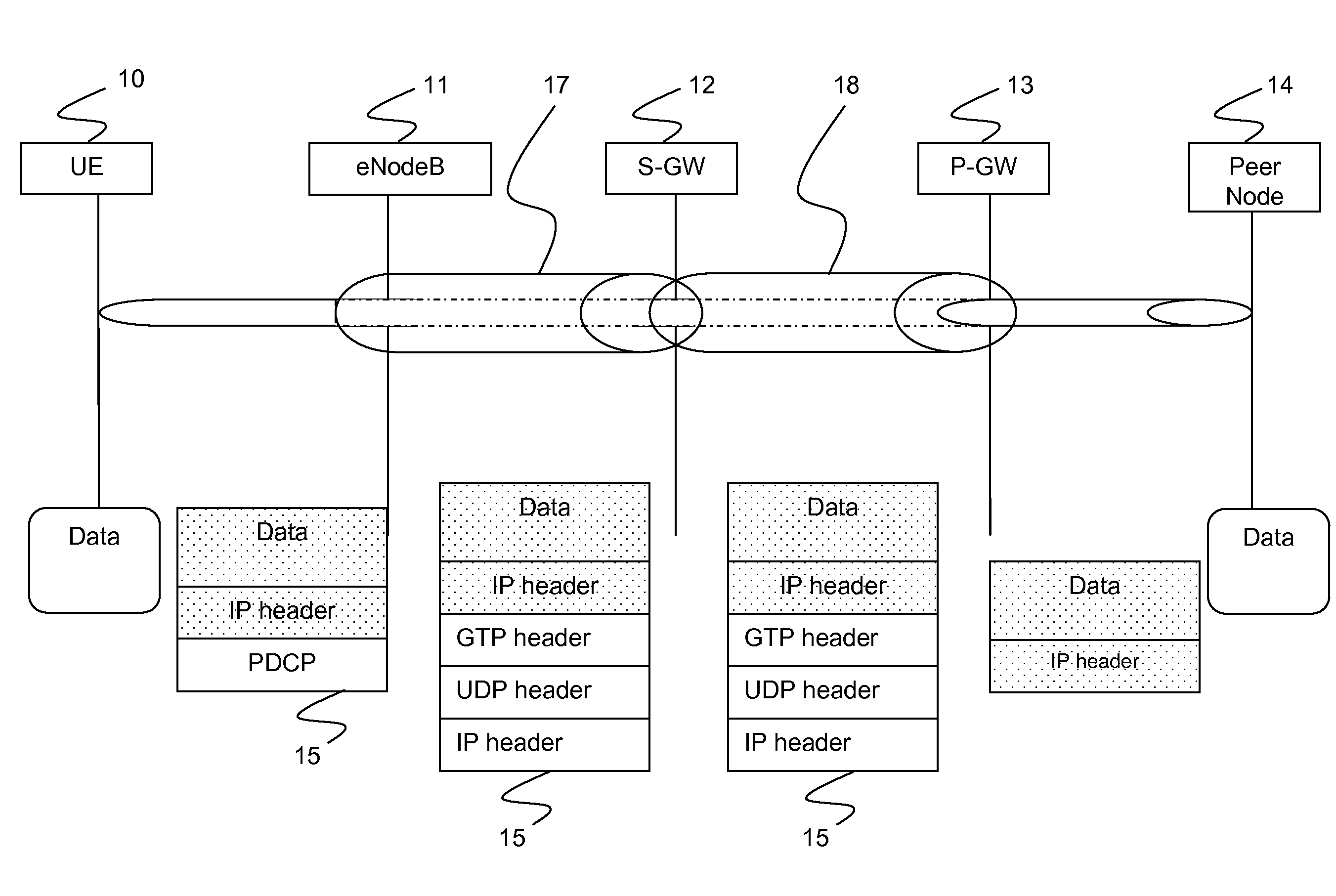
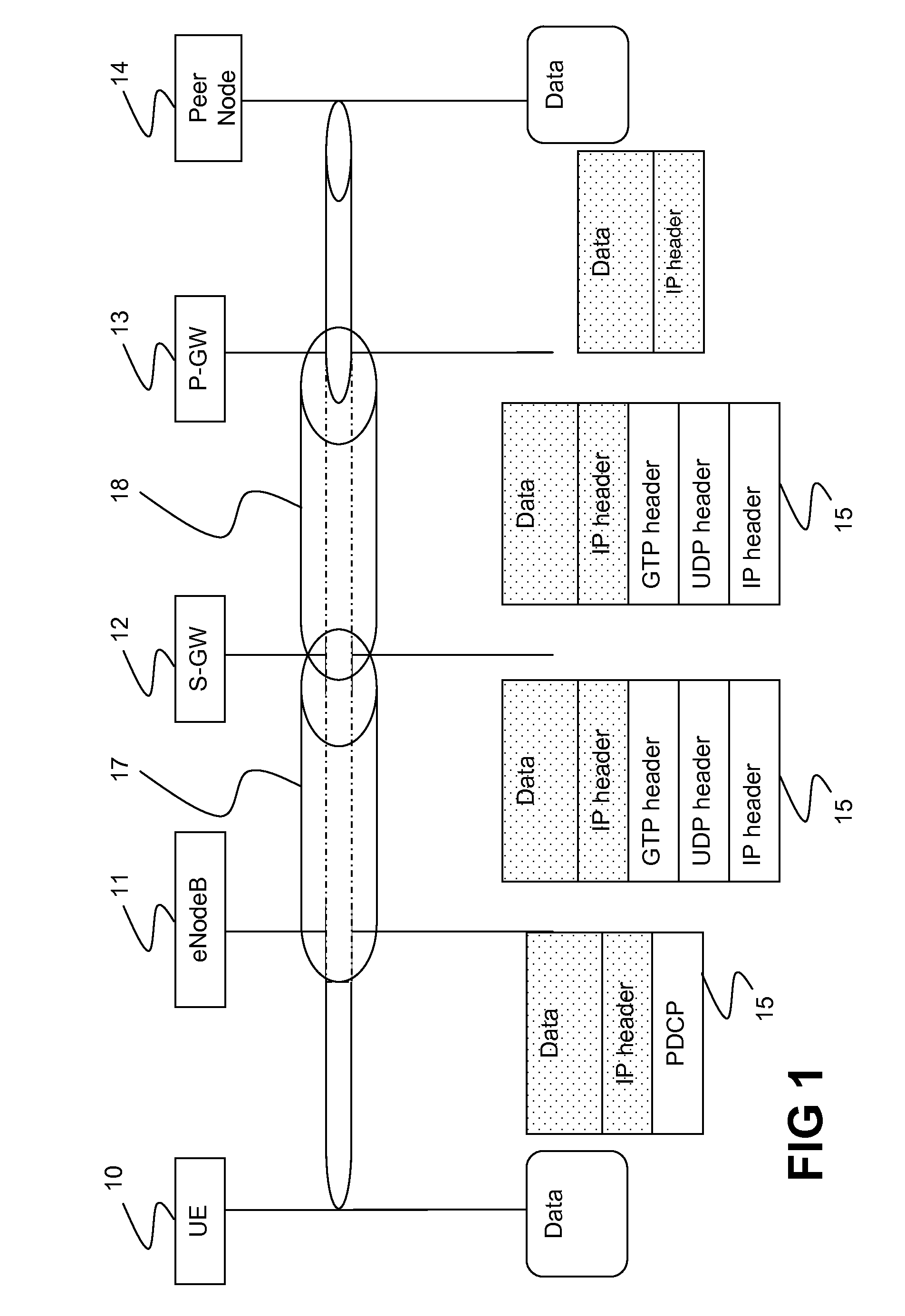
[0025]FIG. 1 illustrates an example of IP packeting through GTP tunnelling. The PCN comprises an UE 10, an eNodeB 11, a Serving Gateway 12, S-GW, and a PDN-Gateway 13, P-GW. The first node will in the following be exemplified by the eNodeB and the second node by the P-GW.

[0026]As shown in the figure, data packets 15 are transmitted through a path formed by a first tunnel 17 extending between the eNodeB...


PUM


Abstract

The present invention relates to a method for improving IP fragmentation and transmission of user payload between a User Equipment, UE 10, and a Peer Node, PN 14. The payload is transmitted through a transmission path enabled by at least a first 17,18 and a second 17,18 established tunnel, said tunnels connecting a first 11, 13 and a second 11,13 node in a Packet Core Network, PCN. The method comprises the steps of:
    • The first node 11,13 fragments 19 at least one received payload packet 15 into fragments 16 on the basis of a minimum Maximum Transmission Unit, MTU, for an upper IP layer of the transmission path.
    • The first node 11,13 encapsulates 20 said fragments at the entry of the first tunnel 17,18.
What particularly characterizes the method is that it further comprises a step where the first node 11,13 determines 21 the MTU for the upper IP layer of the transmission path on the basis of an MTU of a lower IP layer of the transmission path and on the basis of the size of at least one additional tunnel header for the encapsulated fragments 16.

Description

TECHNICAL FIELD[0001]The present invention relates to a method for improving IP fragmentation and transmission of user payload between a User Equipment, UE, and a Peer Node, PN. The present invention also relates to a first node and a packet core network adapted for the same purpose.BACKGROUND[0002]In Packet Core Networks, PCN, the transmitted user payload will be encapsulated and de-encapsulated by adding and removing GPRS Tunneling Protocol, GTP, header. Two consequent GTP tunnels, between the eNodeB and the Serving Gateway, S-GW, and between the S-GW and the PDN Gateway, P-GW, need to be established to successfully transmit packets between the User Equipment, UE, and the Packet Data Network, PDN, while the S-GW acts as the intermediary between the two tunnels.[0003]When the IP packet of user payload is big enough, the final IP packet size after encapsulation could exceed the allowed value. An example of the allowed value is a Maximum Transmission Unit, MTU, of 1500 bytes. As a re...

Claims


Application Information

Patent Timeline
IPC IPC(8): H04L12/56H04L45/74H04L47/36
CPCH04W28/06H04W76/022H04L45/74H04L47/36H04W80/04H04W76/12
Inventor GU, WEIGUO, LEILI, XIAOLIU, DISUN, LIRONGXIA, QI
Owner TELEFON AB LM ERICSSON (PUBL)
Why Eureka
Try Eureka