Rugged Fiber Optic Cable

a fiber optic cable and fiber optic technology, applied in the field of rugged fiber optic cable, can solve the problems of low inherent resistance of loose tubes to crush or impact forces, reduce the ability of loose cables to perform in sharp bends without, and lower fiber density and higher costs. , to achieve the effect of high fiber density and high resistance to crush

Active Publication Date: 2012-06-21
OPTICAL CABLE CORPORATION
View PDF9 Cites 19 Cited by
  • Summary
  • Abstract
  • Description
  • Claims
  • Application Information

AI Technical Summary

Benefits of technology

[0014]As used herein “optical fiber member” means an optical fiber coated with a protective coating and “optical fiber unit” means a plurality of fiber members surrounded by a polymer coating or layer which may bind the fiber members together forming a unit. When an optical fiber unit is constructed in accordance with the teachings of this invention wherein the optical fiber unit polymer coating is in a tight or semi-tight relation with the optical fiber members and a thermoplastic tight buffer is applied directly over the optical fiber unit outer coating, a rugged outdoor rated cable can be constructed which has both high fiber density and high resistance to crush, impact, and moisture exposure. In addition, when flame retardant outdoor rated materials are used, this cable with tight buffer optical fiber unit or units can also be made suitable for both indoor and outdoor applications. For ease of stripping and termination, a release agent may be applied to both the optical fiber members within the optical fiber unit and also between the thermoplastic tight buffer and the fiber unit. Another embodiment allowing direct termination to multi-fiber connectors includes a strength member such as aramid yarn between the optical fiber unit outer coating and the thermoplastic tight buffer. This yarn may contain water blocking elements such as super absorbent polymer coatings or powders for an outdoor or indoor-outdoor design.

Problems solved by technology

This additional material causes the cables to have large diameters, particularly for high fiber counts, resulting in lower fiber density and higher costs.
However, loose tubes have low inherent resistance to crush or impact forces and moisture exposure, so the cable must be rated for low exposure levels or protections must be provided elsewhere in the cable design.
Also, fiber ribbons have a preferential bend axis which may limit the ability of the cable to perform in sharp bends without twisting.
However, these fiber unit loose tube cables are not well suited for indoor and outdoor applications and are not designed for direct termination to multi-fiber connectors.

Method used


Image

  • Rugged Fiber Optic Cable
  • Rugged Fiber Optic Cable
  • Rugged Fiber Optic Cable

Examples


Embodiment Construction

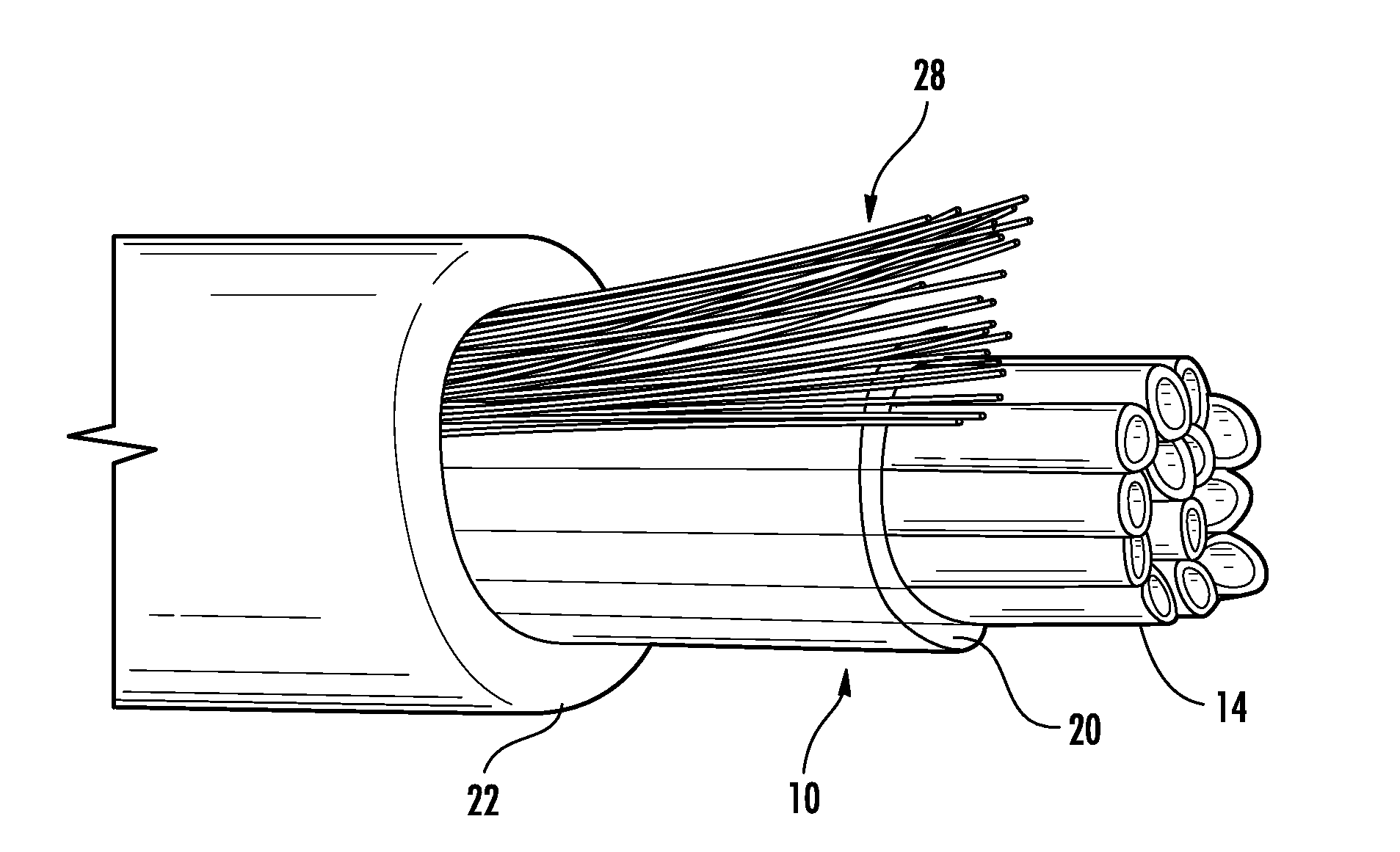
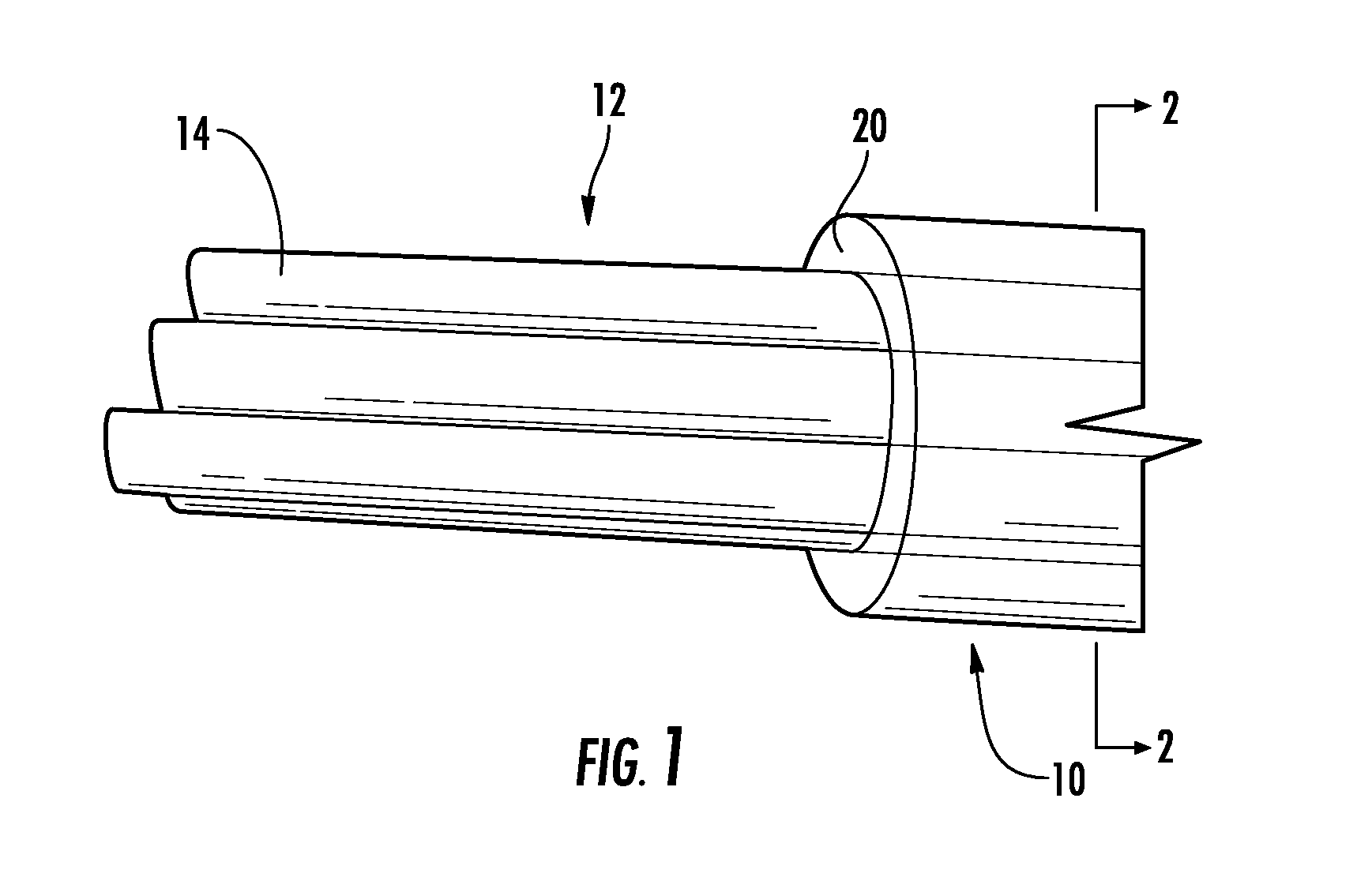
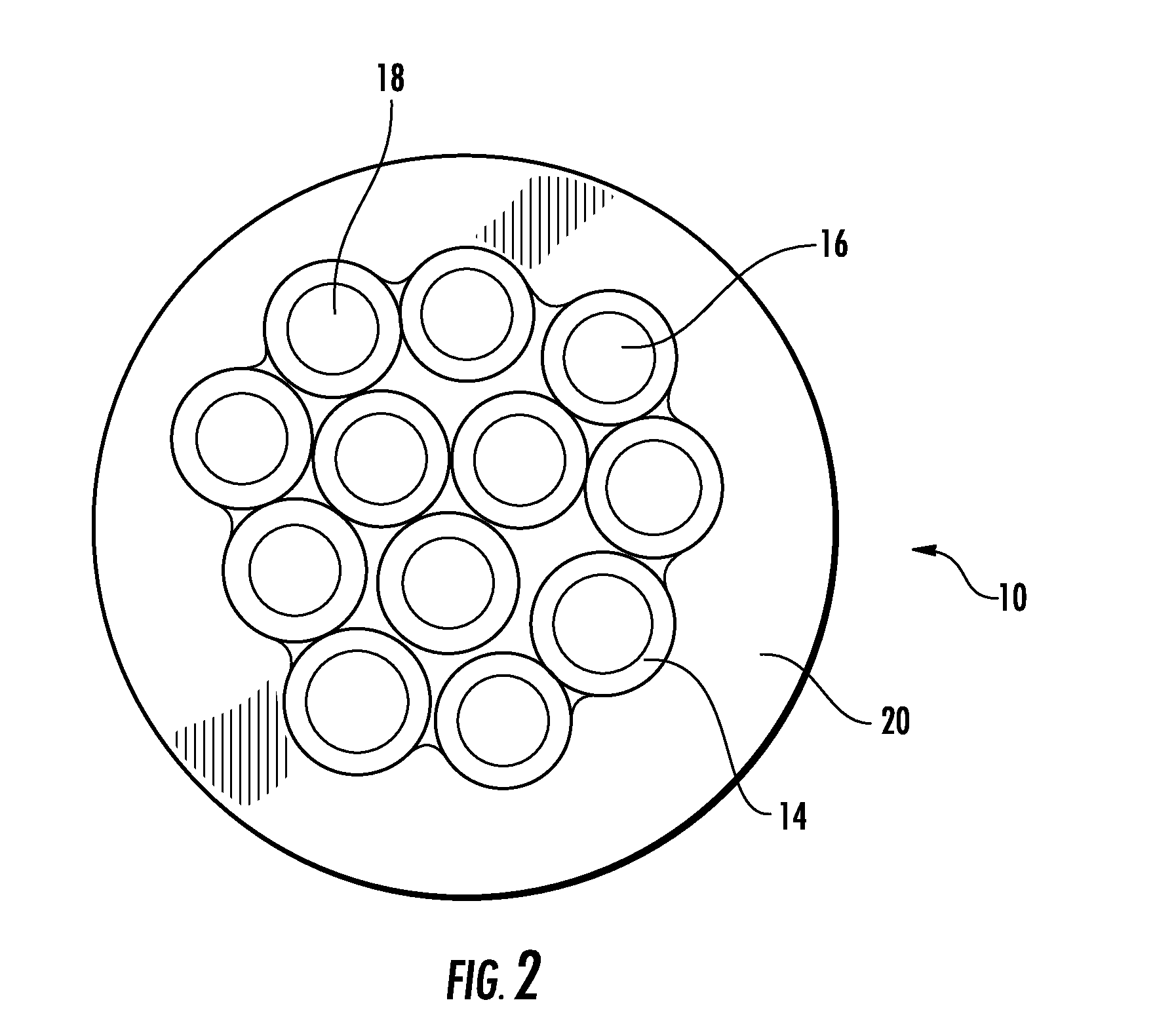
[0029]Referring now more particularly to FIGS. 1-7, there is provided optical fiber unit 10 including a plurality 12 of closely spaced optical fiber members 14 surrounded by coating 20. Each optical fiber member 14 includes optical fiber or filament 16 coated with a protective coating 18. Each optical fiber 16 may be single mode or multi-mode and are preferably bend insensitive fibers as known to those skilled in the art. In the embodiment of FIGS. 3-7, there are twelve individual optical fiber members 14. Each optical fiber member includes a fiber or filament 16, which is preferably made of glass and which is capable of transmitting light. Each optical fiber 16 includes a core surrounded by a cladding as is known to those skilled in the art. Preferably, the optical fibers 16 are approximately 125 microns in diameter, but may be smaller or larger. The protective coating 18 of each optical fiber 16, preferably is made of acrylate. Preferably, each coating is a different color so that...


PUM


Abstract

There is provided an optical fiber cable having a plurality of optical fiber members. Each optical fiber member includes an optical fiber and a protective coating surrounding the optical fiber. A polymer coating surrounds the plurality of optical fiber members and a portion of the polymer coating is located between at least some of the optical fiber members. The optical fiber members and the polymer coating form an optical fiber unit. A tight buffer surrounds the optical fiber unit.

Description

RELATIONSHIP TO PRIOR APPLICATION[0001]This is a U.S. non-provisional application relating to and claiming the benefit of U.S. Provisional Patent Application Ser. No. 61 / 424,275 filed Dec. 17, 2010 and U.S. Provisional Patent Application Ser. No. 61 / 425,578 filed Dec. 21, 2010.BACKGROUND OF THE INVENTION[0002]Fiber optic cables are widely used in the communications industry. For indoor and outdoor applications these cables are generally provided in loose tube and tight buffer cable construction types. Loose tube cables contain one or more optical fibers within one or more loose tubes. Excess fiber length is provided within the loose tube allowing fiber movement during flexure and tensile loading. In tight buffer cables, each individual optical fiber is contained under a thermoplastic sheath applied directly to the fiber protective coating. This thermoplastic tight buffer sheath provides added protection for each fiber for crush and impact forces during handling and installation.[000...

Claims


Application Information

Patent Timeline
Patent Type & Authority Applications(United States)
IPC IPC(8): G02B6/44
CPCG02B6/441G02B6/4494G02B6/4434G02B6/4432G02B6/44384
Inventor LEONARD, TEDDY W.STOVER, MICHAEL A.PLASKI, AARON J.
Owner OPTICAL CABLE CORPORATION
Why Eureka
Try Eureka