Connection member, method of manufacturing the same and connection structure

a technology of connecting parts and manufacturing methods, applied in the directions of knotting, weaving, transportation and packaging, etc., can solve the problems of difficult handling, difficult connection of power supply wires, and difficulty in connection operation, so as to reduce the number of parts, facilitate sewing, and connect the electric wire for power feeding.

Inactive Publication Date: 2012-06-21
TOYOTA BOSHOKU KK
View PDF10 Cites 68 Cited by
  • Summary
  • Abstract
  • Description
  • Claims
  • Application Information

AI Technical Summary

Benefits of technology

[0013]According to the connection member as described above, since the connection terminal is attached to the exposed conductive wires in advance, when sewing a covering material, to which the conductive fabric having the connection member connected thereto is adhered, and the other covering material each other and thus manufacturing a seat cover of a vehicle, it is possible to easily perform the sewing and to easily connect the electric wire for power feeding. Also, since the connection terminal is directly attached to the conductive wires of the connection member, it is possible to reduce the number of parts, compared to a case where the conductive wires and the connection terminal are connected via a drawn lead wire. Furthermore, compared to a case where the connection terminal is attached after the seat cover is manufactured, it is possible to easily handle it and to increase the reliability of the connection by caulking and the like.
[0014]In addition, when the connection member is a band-shaped woven fabric and the conductive wires configure a part of the warp and at least non-conductive threads are used for the weft, it is possible to easily make a band-shaped connection member having a predetermined length.
[0015]According to the above method of manufacturing the connection member, since the original band-shaped member is used which is woven by using the conductive wires for a part of the warp and using at least non-conductive threads for the weft, it is easy to expose the conductive wires at the end portion of the original band-shaped member. As a result, it is possible to easily manufacture the connection member with simple process and convenient operation.
[0016]Also, in the exposing process, when the conductive wires of the end portion of the original band-shaped member are exposed by unthreading the non-conductive threads woven as the weft, it is possible to expose the conductive wires more easily with convenient operation.
[0017]According to the above connection structure, the conductive threads of the conductive fabric and the conductive wires of the connection member are connected and the connection structure is adhered on a backside of the covering material of a seat cushion and a seatback of a vehicle, particularly automobile. Thus, the connection structure can be useful for a heater member of a seat that can warm a passenger from lower body and the like under low temperature conditions such as winter.

Problems solved by technology

However, if the heat generation and retention member described in the above JP-UM-A-3119584 is used as the heater member of a vehicle seat, when the covering material, to which the heat generation and retention member is adhered, and the other covering material are sewn to manufacture a seat cover, the power supply wire, which is connected to the second conductor in advance, becomes an obstacle, so that it is difficult to handle.
Also, it is not easy to connect the power supply wire after manufacturing the seat cover.
Accordingly, when the electrode plates are connected after manufacturing the seat cover, it is not easy to perform the connection operation.

Method used


Image

  • Connection member, method of manufacturing the same and connection structure
  • Connection member, method of manufacturing the same and connection structure
  • Connection member, method of manufacturing the same and connection structure

Examples


Embodiment Construction

[0026]Hereinafter, illustrative embodiments of the present invention will be specifically described with reference to FIGS. 1A to 3.

[0027]The following description is just exemplary and is provided to exemplarily explain an illustrative embodiment of the present invention and to understand the gist and conceptual features of the present invention most efficiently and easily. Therefore, the structural details are not provided beyond the extent necessary for the basic understanding of the present invention, and one skilled in the art can clearly appreciate how illustrative embodiments of the present invention are actually implemented by the below descriptions referring to the drawings.

[0028](1) Connection Member

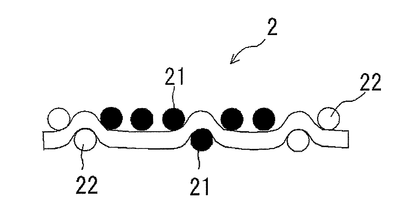
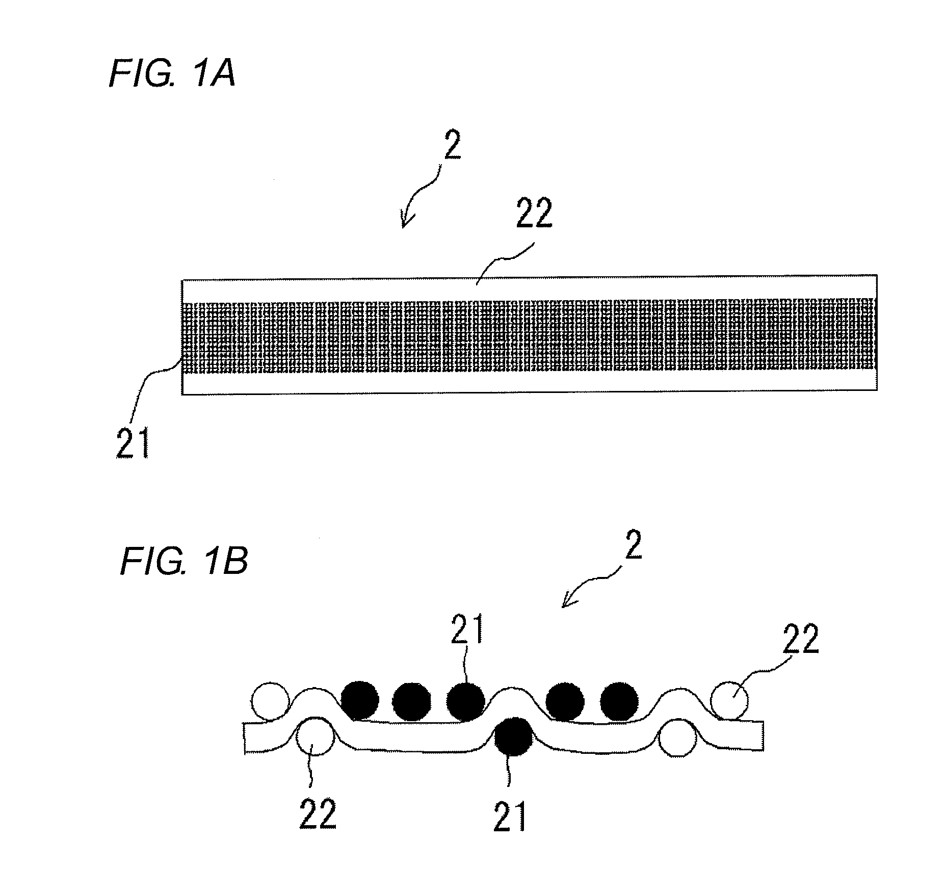
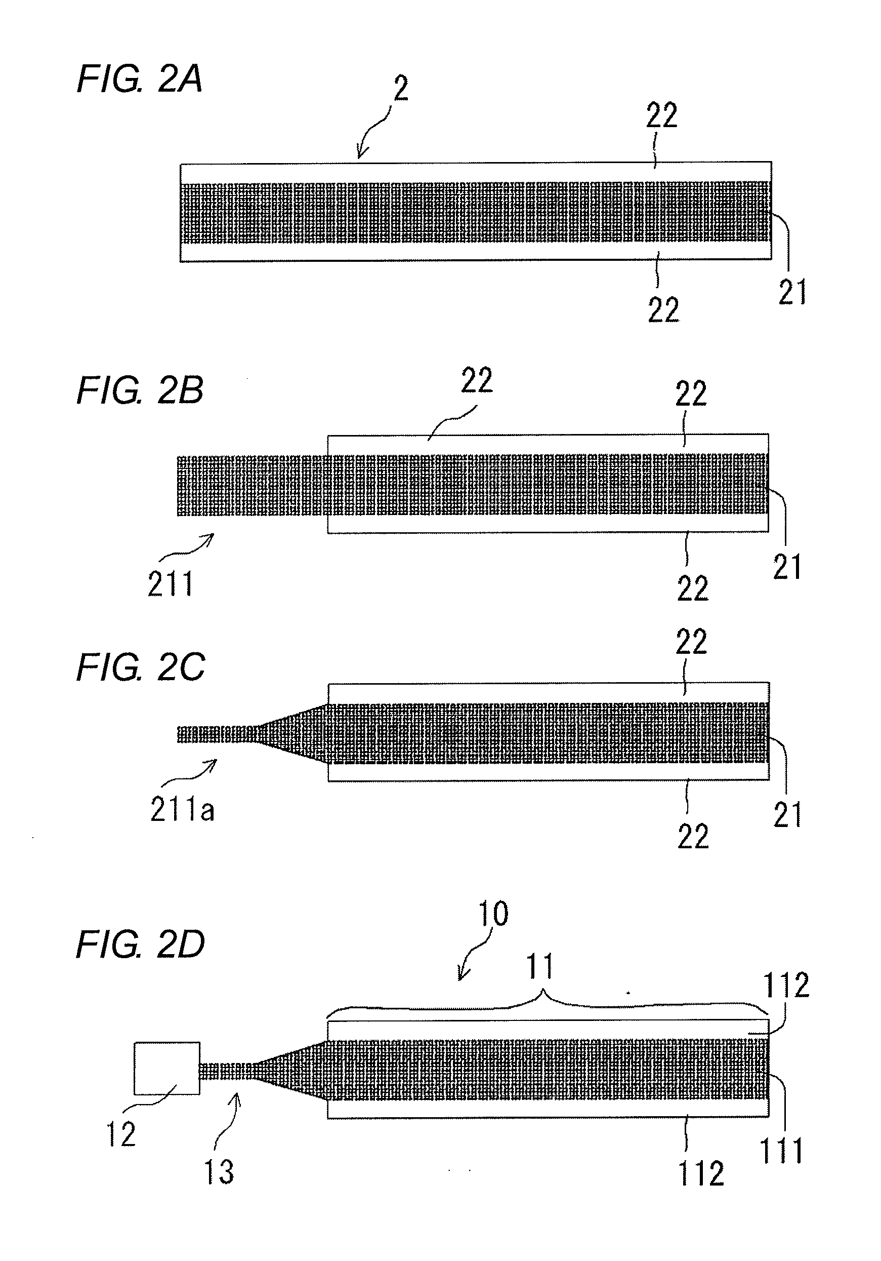
[0029]A connection member according to an illustrative embodiment (refer to a connection member 10 of FIG. 2D) is electrically connected to a conductive fabric (refer to a conductive fabric 101 of FIG. 3) having conductive threads (refer to conductive threads 101a of the conduc...


PUM

PropertyMeasurementUnit
diameteraaaaaaaaaa
diameteraaaaaaaaaa
diameteraaaaaaaaaa

Abstract

A connection member which is electrically connected to a conductive fabric having conductive threads, a method for manufacturing the connection member, and a connection structure are provided. The connection member includes a band-shaped part including conductive wires which extend in a longitudinal direction, and a connection terminal which is attached to an end portion of the conductive wires. The method includes forming an original band-shaped member by weaving while using the conductive wires for a part of warp and using at least non-conductive threads for weft; exposing the conductive wires at an end portion of the original band-shaped member;and attaching a connection terminal to the exposed conductive wires. The connection structure includes the conductive fabric and the connection member, and the conductive wires of the connection member are electrically connected to the conductive threads exposed from the conductive fabric.

Description

BACKGROUND OF THE INVENTION[0001]1. Field of the Invention[0002]The present invention relates to a connection member, a method of manufacturing the same and a connection structure.[0003]2. Description of the Related Art[0004]Conventionally, there have been known a variety of heater members in which conductive threads are used for a part of threads configuring woven and knitted fabrics and electric current is applied to the conductive threads to generate heat and to thus increase the temperature. The heater members are used for various applications. For example, a seat for a vehicle, particularly automobile has been known in which a heater member is adhered on a backside of a covering material such as seat cushion and can warm a passenger from a lower side and the like under low temperature conditions such as in winter. In addition, the heater member is configured such that an end portion of the heater member is connected with a connection member, conductive threads of a conductive f...

Claims


Application Information

Patent Timeline
Patent Type & Authority Applications(United States)
IPC IPC(8): H01R11/11D03D15/00H01R43/00
CPCH05B3/342H05B2203/016H01R4/12D10B2401/16H05B2203/015D10B2501/04Y10T29/49174D03D3/005D10B2505/12D10B2503/04D03D15/587
Inventor KATO, KOHEIAKAIKE, FUMITOSHI
Owner TOYOTA BOSHOKU KK
Why Eureka
Try Eureka