Wireless power transmission system, wireless power transmitting apparatus and wireless power receiving apparatus

a wireless transmission and wireless technology, applied in the field of wireless power transmission technology, can solve the problems of inability to efficiently focus, electromagnetic waves generated by the rf signal may be harmful to biology, and the application of the rf signal in the field of biomedical applications (such as implantable medical devices) still has some limitations to overcome, so as to improve the efficiency of wireless power transmission

Inactive Publication Date: 2012-06-21
LI PAI CHI
View PDF8 Cites 286 Cited by
  • Summary
  • Abstract
  • Description
  • Claims
  • Application Information

AI Technical Summary

Benefits of technology

[0017]In one embodiment, the above mentioned ultrasonic receiving unit is equipped with a single ultrasonic receiving probe, so that the receiving of a sound field is facilitated to be controlled in a fixed focusing manner.
[0022]In summary, the present invention uses the focused ultrasonic wave to achieve wireless power transmission. Because the focused ultrasonic wave has an advantage of definite energy transmission path in a specific space, the ultrasonic power can be focused to the receiving apparatus, and therefore the efficiency of wireless power transmission is improved. Moreover, because the ultrasonic wave does not generate ionizing radiation, and thus is suitable for the biomedical applications (such as applied into implantable medical devices). In addition, the focused ultrasonic wave can be used for data transmission and thereby achieving various applications.

Problems solved by technology

However, the applications of the RF signal in the area of biomedical applications (such as implantable medical devices) still have some limitations needed to be overcome.
In particular, a first one of the reasons is that electromagnetic waves generated from the RF signal may be harmful to biology, a second one of the reasons is that the RF signal located within a general frequency range (for example, 3 KHz˜300 MHz) cannot be efficiently focused at a relatively short distance (for example, within 1 m), and a third one of the reasons is that the RF signal located within the ultra high frequency range (for example, higher than 300 MHz) is easily to be absorbed by materials, so as not easily to be transmitted.

Method used


Image

  • Wireless power transmission system, wireless power transmitting apparatus and wireless power receiving apparatus
  • Wireless power transmission system, wireless power transmitting apparatus and wireless power receiving apparatus
  • Wireless power transmission system, wireless power transmitting apparatus and wireless power receiving apparatus

Examples


Embodiment Construction

[0026]The present invention will now be described more specifically with reference to the following embodiments. It is to be noted that the following descriptions of preferred embodiments of this invention are presented herein for purpose of illustration and description only. It is not intended to be exhaustive or to be limited to the precise form disclosed.

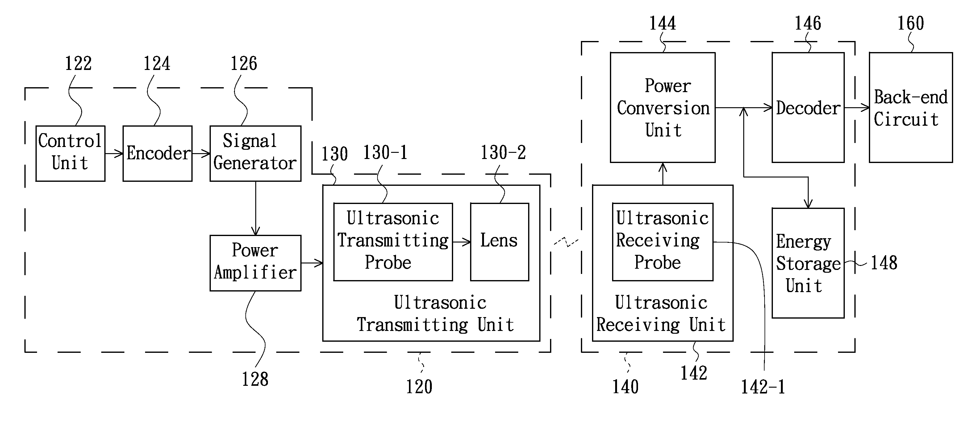
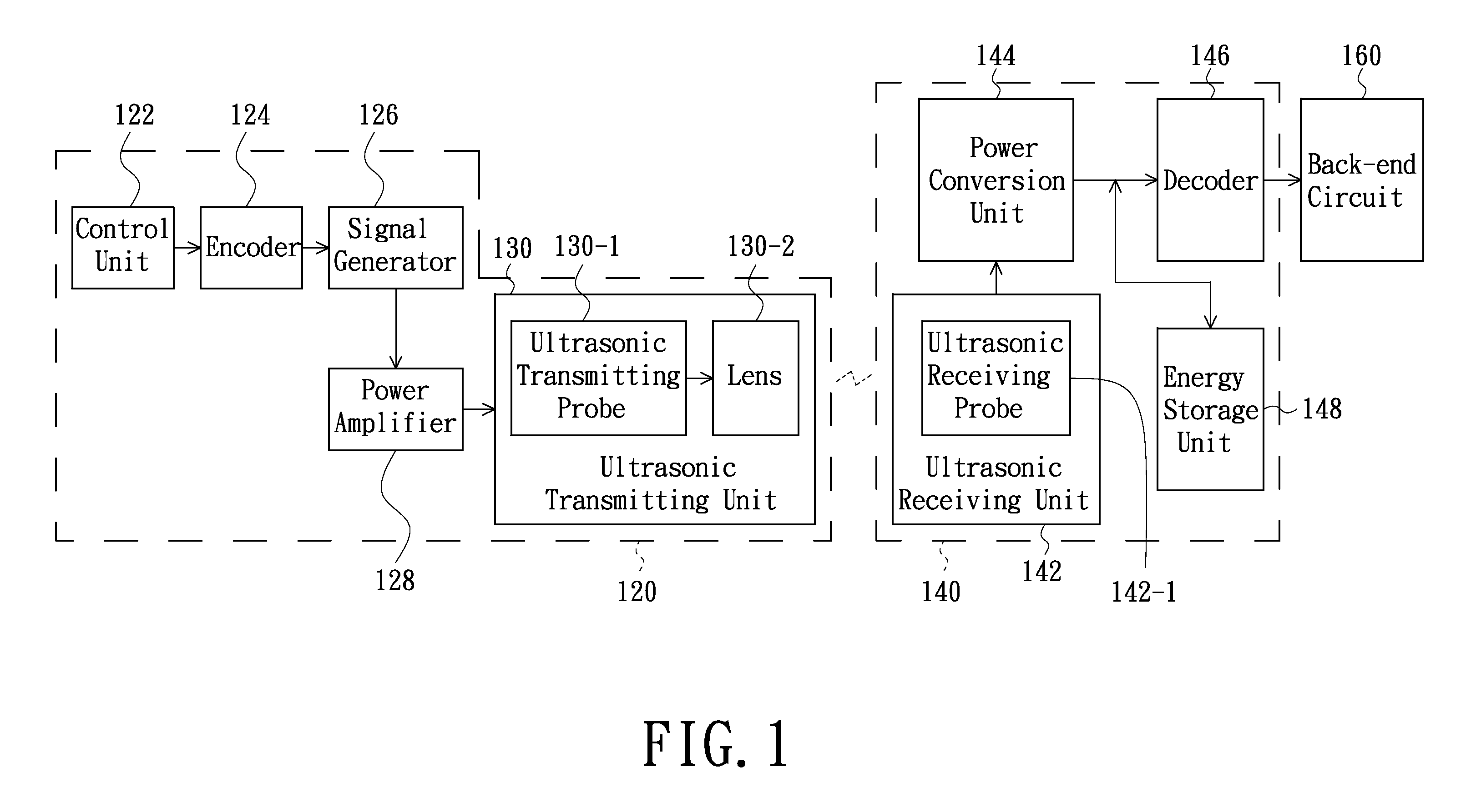
[0027]FIG. 1 is a schematic block diagram of a wireless power transmission system in accordance with an embodiment of the present invention. As depicted in FIG. 1, the wireless power transmission system comprises a wireless power transmitting apparatus 120 and a wireless power receiving apparatus 140. The wireless power transmission system is configured (i.e., structured and arranged) for supplying electrical power energy (i.e., operating power supply) to a back-end circuit 160 for use. The wireless power receiving apparatus 140 and the back-end circuit 160 can be integrated to be a single device, such as an implantable medical d...


PUM


Abstract

A wireless power transmission system includes a wireless power transmitting apparatus and a wireless power receiving apparatus. The wireless power transmitting apparatus includes a signal generator and an ultrasonic transmitting unit. The ultrasonic transmitting unit generates and outputs a focused ultrasonic wave according to a signal outputted from the signal generator. The wireless power receiving apparatus includes an ultrasonic receiving unit and a power conversion unit. The ultrasonic receiving unit receives the focused ultrasonic wave outputted from the wireless power transmitting apparatus and converts the focused ultrasonic wave into electrical power energy. The power conversion unit performs a power conversion on the electrical power energy and thereby provides the converted electrical power energy to a back-end circuit. The ultrasonic signal can also be encoded in the transmitting unit and subsequently decoded in the receiving unit as a means to remotely control the back-end circuit in the receiving unit.

Description

FIELD OF THE INVENTION[0001]The present invention relates to a wireless power transmission technology, and more particularly to a wireless power transmission system utilizing a focused ultrasonic wave for the transmission of wireless power, and a wireless power transmitting apparatus and a wireless power receiving apparatus of such wireless power transmission system.BACKGROUND OF THE INVENTION[0002]So far, the technologies of transmitting wireless power via radio frequency (RF) signal have been developed. For example, the U.S. Pat. No. 7,068,991 has disclosed a related technology about the wireless power transmission via the RF signal and its applications.[0003]However, the applications of the RF signal in the area of biomedical applications (such as implantable medical devices) still have some limitations needed to be overcome. These limitations are mainly resulted by three reasons. In particular, a first one of the reasons is that electromagnetic waves generated from the RF signal...

Claims


Application Information

Patent Timeline
Patent Type & Authority Applications(United States)
IPC IPC(8): H04W52/04H02J4/00
CPCH04B11/00
Inventor LI, PAI-CHI
Owner LI PAI CHI
Why Eureka
Try Eureka