Leadless Pacemaker with Radial Fixation Mechanism

a technology of radial fixation and lead-less pacemakers, which is applied in the direction of internal electrodes, transvascular endocardial electrodes, therapy, etc., can solve the problems of subcutaneous pulse generators that can exhibit erosion, discomfort, or irritation, and prolong patient recovery, so as to reduce compression force and reduce compression force

Active Publication Date: 2012-06-21
PACESETTER INC
View PDF13 Cites 203 Cited by
  • Summary
  • Abstract
  • Description
  • Claims
  • Application Information

AI Technical Summary

Benefits of technology

[0012]In some embodiments, the pacing electrode comprises a dome shape. In additional embodiments, the pacing electrode is attached to the housing via a compliant spring to reduce compression force against the heart tissue. In another embodiment, the pacing electrode is attached to the housing via a silicon adhesive to reduce compression force against the heart tissue.

Problems solved by technology

Although more than one hundred thousand conventional cardiac pacing systems are implanted annually, various well-known difficulties exist, of which a few will be cited.
For example, a pulse generator, when located subcutaneously, presents a bulge in the skin that patients can find unsightly, unpleasant, or irritating, and which patients can subconsciously or obsessively manipulate or “twiddle”.
Even without persistent manipulation, subcutaneous pulse generators can exhibit erosion, extrusion, infection, and disconnection, insulation damage, or conductor breakage at the wire leads.
Although sub-muscular or abdominal placement can address some concerns, such placement involves a more difficult surgical procedure for implantation and adjustment, which can prolong patient recovery.
This briefly described complex connection between connectors and leads provides multiple opportunities for malfunction.
Other problematic aspects of conventional pacemakers relate to the separately implanted pulse generator and the pacing leads.
By way of another example, the pacing leads, in particular, can become a site of infection and morbidity.

Method used


Image

  • Leadless Pacemaker with Radial Fixation Mechanism
  • Leadless Pacemaker with Radial Fixation Mechanism
  • Leadless Pacemaker with Radial Fixation Mechanism

Examples


Embodiment Construction

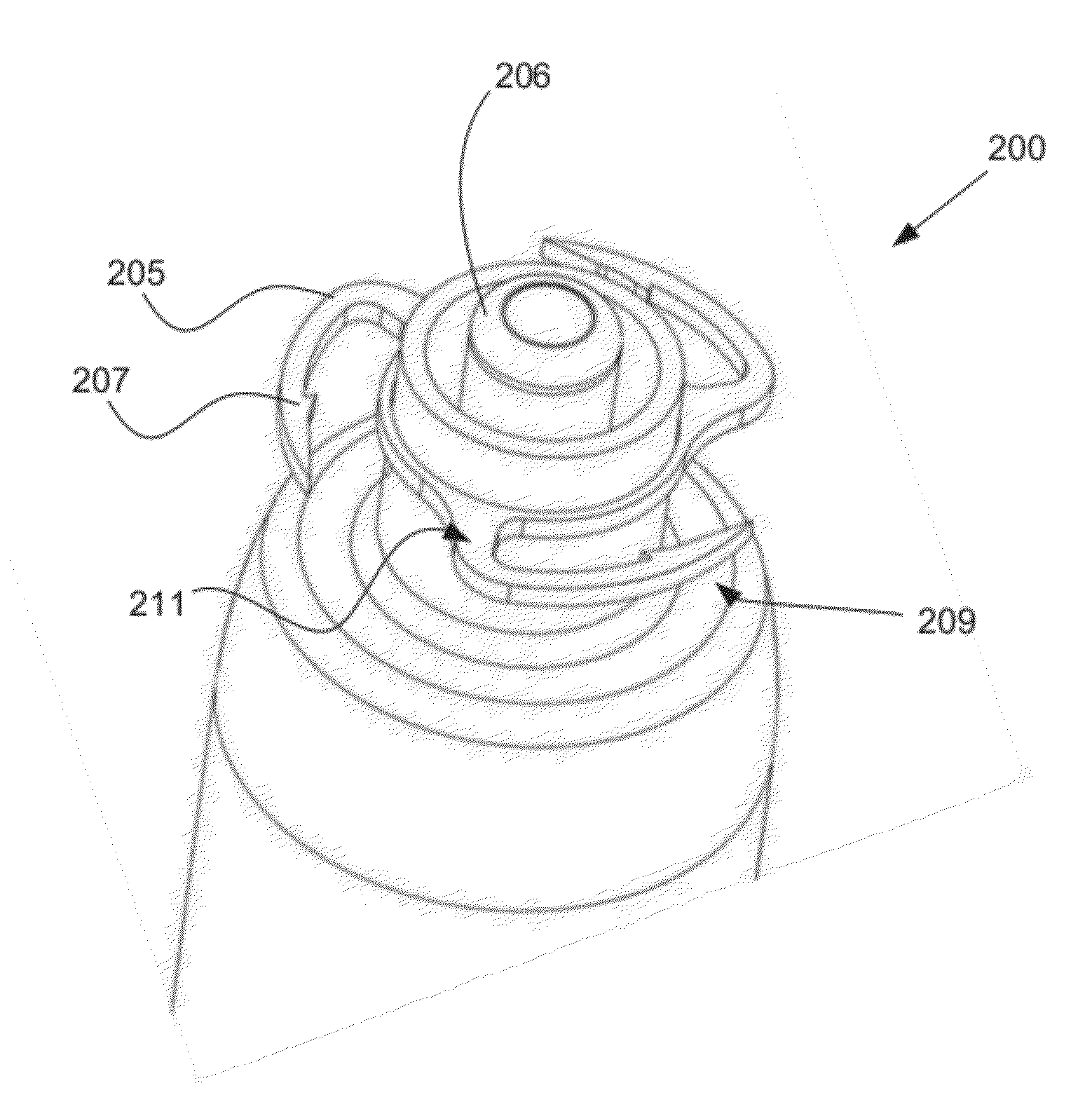
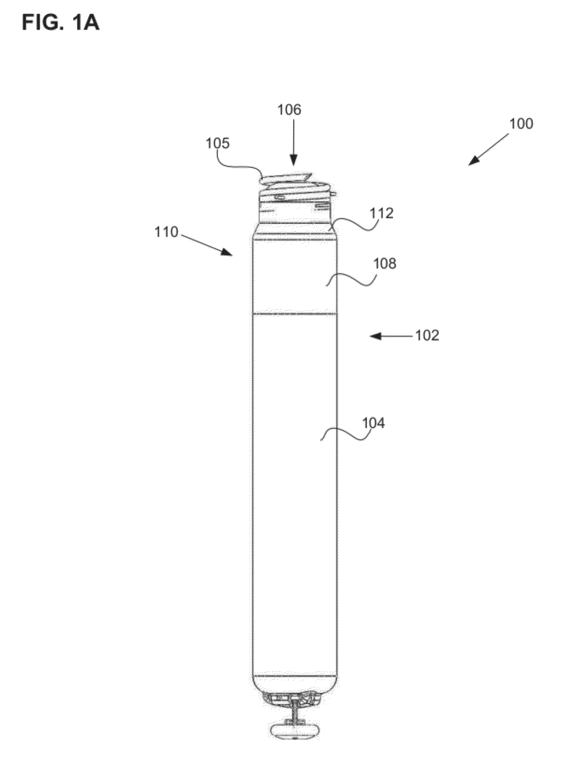
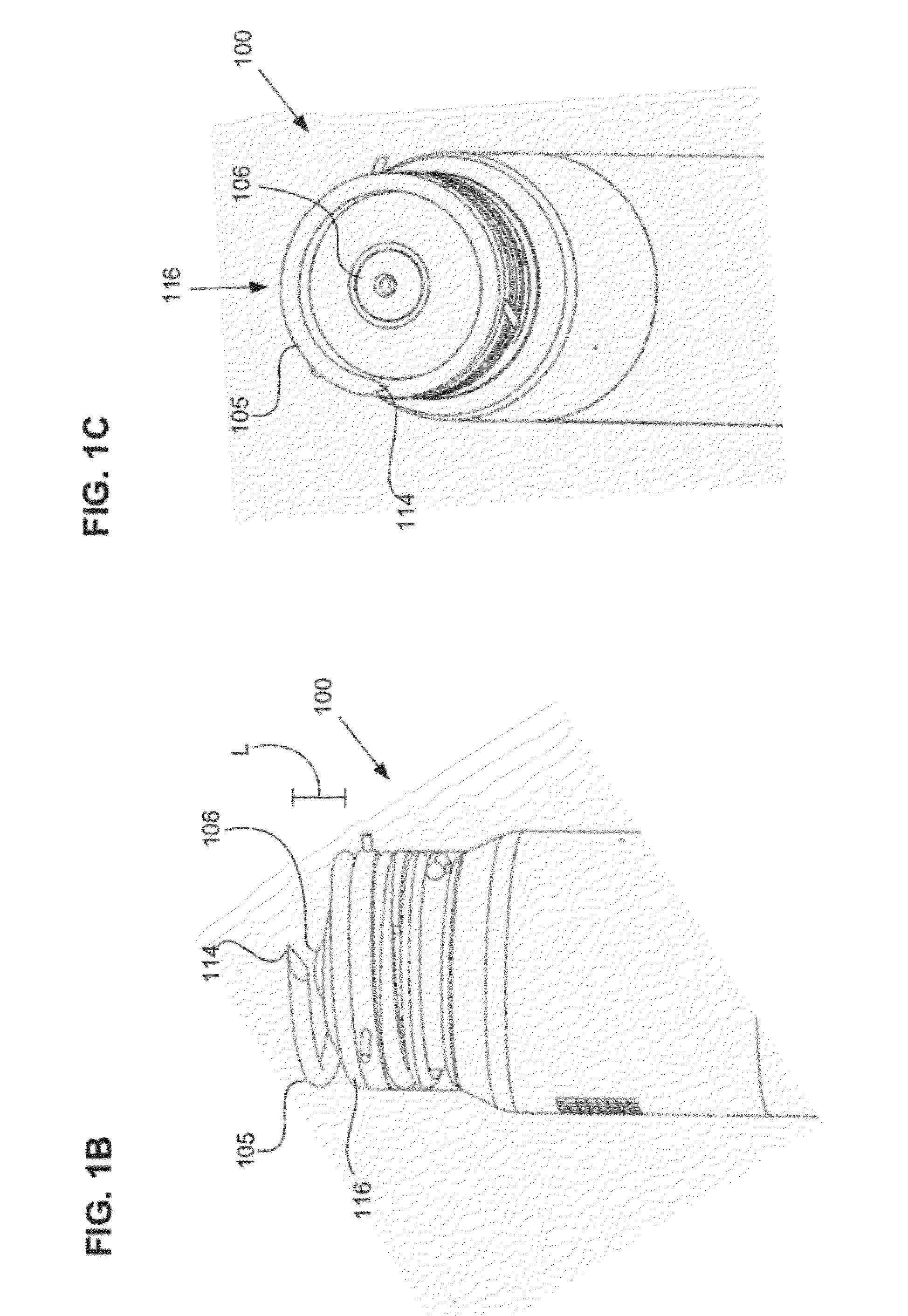
[0023]Various embodiments of a leadless cardiac pacemaker having at least one radial fixation mechanism are provided. A leadless cardiac pacemaker can communicate by conducted communication, representing a substantial departure from conventional pacing systems. For example, an illustrative cardiac pacing system can perform cardiac pacing that has many of the advantages of conventional cardiac pacemakers while extending performance, functionality, and operating characteristics with one or more of several improvements.

[0024]In some embodiments of a cardiac pacing system, cardiac pacing is provided without a pulse generator located in the pectoral region or abdomen, without an electrode-lead separate from the pulse generator, without a communication coil or antenna, and without an additional requirement on battery power for transmitted communication.

[0025]An embodiment of a cardiac pacing system configured to attain these characteristics comprises a leadless cardiac pacemaker that is s...


PUM


Abstract

A leadless cardiac pacemaker having a radial fixation mechanism is provided. The cardiac pacemaker can include fixation mechanism separate from a pacing electrode and having a diameter equal to or less than the outer diameter of the pacemaker. The fixation mechanism can allow the pacemaker to be inserted into tissue with less than 2 rotations of the pacemaker to place the pacing electrode in contact with the tissue. In some embodiments, the fixation mechanism can comprise a plurality of hooks or protrusions positioned near a distal portion of the pacemaker. The fixation mechanism(s) can be configured to penetrate the endocardium of the patient and reside mostly within the myocardium. Methods of delivering the leadless cardiac pacemaker into the heart are also provided.

Description

CROSS REFERENCE TO RELATED APPLICATIONS[0001]This application claims the benefit of U.S. Provisional Patent Application No. 61 / 425,064, filed Dec. 20, 2010, titled “LEADLESS PACEMAKER WITH RADIAL FIXATION MECHANISM”, which application is incorporated herein by reference in its entirety.INCORPORATION BY REFERENCE[0002]All publications and patent applications mentioned in this specification are herein incorporated by reference to the same extent as if each individual publication or patent application was specifically and individually indicated to be incorporated by reference.FIELD[0003]The present disclosure relates to leadless cardiac pacemakers, and more particularly, to features and methods by which they are attached to heart tissue. More specifically, the present disclosure relates to features and methods for attaching a leadless cardiac pacemaker to tissue with a radial fixation mechanism.BACKGROUND[0004]Cardiac pacing by an artificial pacemaker provides an electrical stimulation...

Claims


Application Information

Patent Timeline
Patent Type & Authority Applications(United States)
IPC IPC(8): A61N1/05
CPCA61N1/057A61N1/3756A61N1/375A61N1/37205A61N1/37512A61N1/37518A61N1/0573
Inventor KHAIRKHAHAN, ALEXANDEROSTROFF, ALANVARADY, ERICPASPA, PAUL
Owner PACESETTER INC
Why Eureka
Try Eureka