Electronic condensate overflow switch

a technology of condensate overflow and switch, which is applied in the field of electronic condensate overflow switches, can solve the problems of extremely low heat dissipation and extremely low on-state resistance of power mosfets relative to diode switches and other types of switches, and achieves low on-state resistance, low heat dissipation, and efficient sensing

Inactive Publication Date: 2012-06-21
RECTORSEAL
View PDF0 Cites 18 Cited by
  • Summary
  • Abstract
  • Description
  • Claims
  • Application Information

AI Technical Summary

Benefits of technology

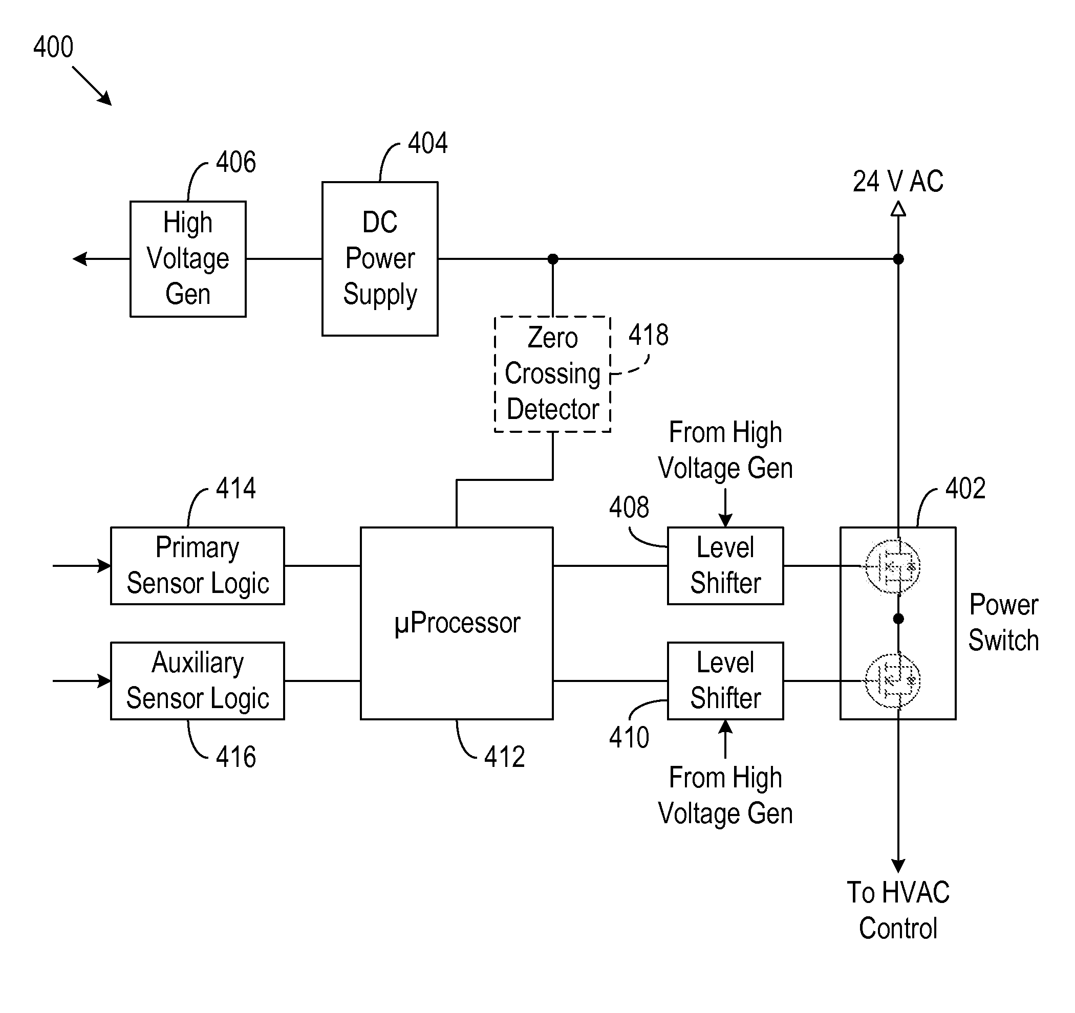
[0015]The disclosed embodiments are directed to an electronic condensate overflow switch and methods and systems therefor. The disclosed condensate overflow switch derives operational power directly from an AC main and does not need an external power supply. As such, the condensate overflow switch does not need a separate, reference ground line, and therefore does not require configuration in a particular polarity. In addition, the disclosed condensate overflow switch uses power MOSFETs as an in-line s

Problems solved by technology

The power MOSFETs have extremely low on-state resistance and, therefore, extrem

Method used


Image

  • Electronic condensate overflow switch
  • Electronic condensate overflow switch
  • Electronic condensate overflow switch

Examples


Embodiment Construction

[0028]The figures described above and the written description of specific structures and functions below are not presented to limit the scope of what has been invented or the scope of the appended claims. Rather, the figures and written description are provided to teach any person skilled in the art to make and use the embodiments for which patent protection is sought. Those skilled in the art will appreciate that not all features of a commercial embodiment are described or shown for the sake of clarity and understanding. Persons of skill in this art will also appreciate that the development of an actual commercial embodiment incorporating aspects disclosed herein will require numerous implementation-specific decisions to achieve the developer's ultimate goal for the commercial embodiment. Such implementation-specific decisions may include, and likely are not limited to, compliance with system-related, business-related, government-related, and other constraints, which may vary by sp...


PUM

PropertyMeasurementUnit
Poweraaaaaaaaaa
Polarityaaaaaaaaaa
Electrical resistanceaaaaaaaaaa

Abstract

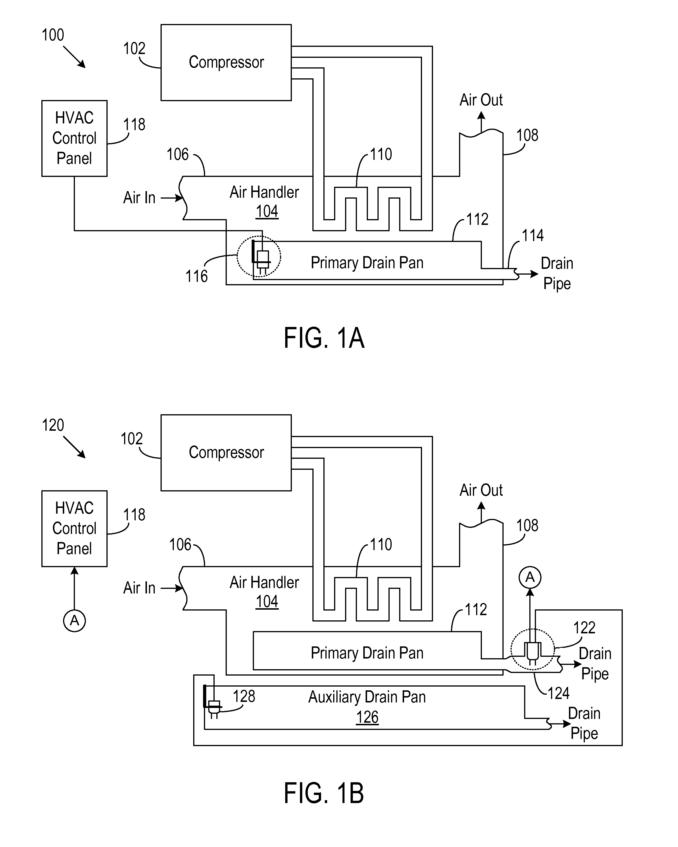
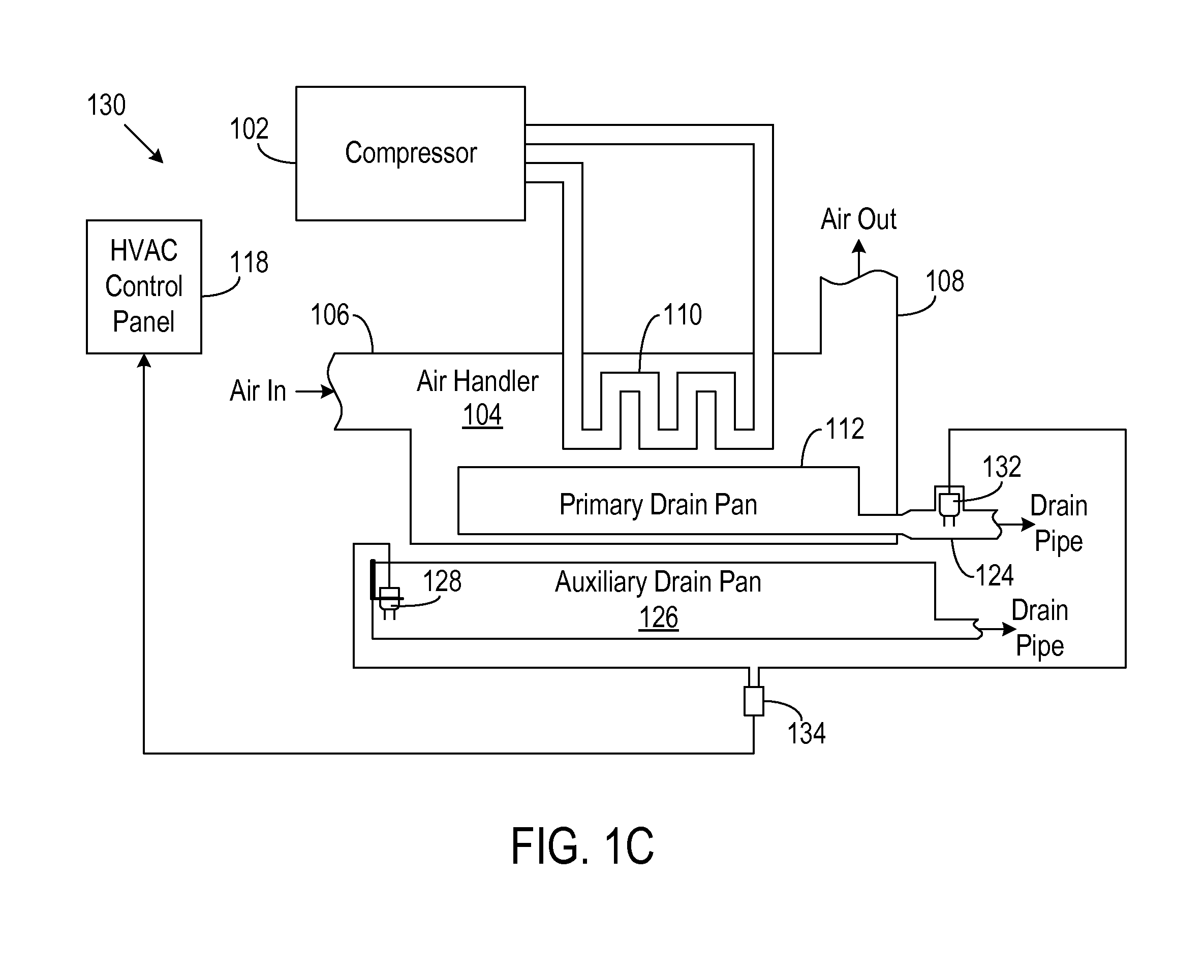
A non-polarized electronic condensate overflow switch uses microprocessor-controlled low-resistance MOSFETs to connect and disconnect power to an HVAC system. The condensate overflow switch derives operational power directly from an AC main and does not need an external power supply or a separate, reference ground line, and therefore does not require configuration in a particular polarity. The microprocessor controls the turning on and off of the power MOSFETs as needed when condensate overflow is detected and also provides more efficient sensing of condensate overflow and other operations, thus minimizing the power needed by the condensate overflow switch. Such a non-polarized electronic condensate overflow switch may be installed within a drain pan, in line with an outlet of the drain pan, or at a remote location away from the drain pan.

Description

CROSS REFERENCE TO RELATED APPLICATIONS[0001]Not applicable.STATEMENT REGARDING FEDERALLY SPONSORED RESEARCH[0002]Not applicable.COPYRIGHT NOTIFICATION[0003]Portions of this patent disclosure contain materials that are subject to copyright protection. The copyright owner has no objection to the facsimile reproduction by anyone of the patent document or the patent disclosure as it appears in the Patent and Trademark Office (PTO) patent file or records, but otherwise reserves all copyright rights.REFERENCE TO APPENDIX[0004]Not applicable.BACKGROUND OF THE INVENTION[0005]1. Field of the Invention[0006]This disclosure relates generally to electronic condensate overflow switches. More particularly, the present disclosure relates to electronic condensate overflow switches that use microprocessor-controlled low-resistance MOSFETs as power switches.[0007]2. Description of the Related Art[0008]Heating, ventilating, and air conditioning (HVAC) systems typically employ evaporator coils to dehu...

Claims


Application Information

Patent Timeline
IPC IPC(8): H01H35/00G05D23/19
CPCG01F23/243H02M2001/0006H02M1/0006
Inventor MADALA, SRIDHAR
Owner RECTORSEAL
Why Eureka
Try Eureka