Motor driven vehicle

a motor and vehicle technology, applied in the direction of propulsion by batteries/cells, cycle equipment, optical signals, etc., can solve the problems of increasing the number of components, complicating the structure reducing the efficiency of the vehicle body, so as to reduce the influence of the harness, reduce the deformation of the duct, and facilitate the effect of charging work

Active Publication Date: 2012-06-28
HONDA MOTOR CO LTD
View PDF9 Cites 12 Cited by
  • Summary
  • Abstract
  • Description
  • Claims
  • Application Information

AI Technical Summary

Benefits of technology

[0018]Also, as a result of certain embodiments, it is possible to reduce the deformation of the duct due to the swing movement of the swing arm, which can reduce an influence on the harness.
[0019]Furthermore, in certain embodiments, the charging line of the battery can be taken out from the vehicle body side such as, for example, a storage box below the seat of the motorcycle. Thus, convenience during charging work can be enhanced.
[0020]In embodiments where, the duct is connected on the other end side to the vehicle body side connecting portion provided on the motor driven vehicle, the duct can be supported stably.
[0021]In embodiments where, the motor driven vehicle is a scooter-type motor driven two-wheeled vehicle, and the vehicle body side connecting portion is the storage box installed below the seat of the motor driven vehicle, the duct has the other end side connected to the storage box. For example, the charging line can be taken out from the inside of the storage box, which facilitates work for connection with the external power source, thereby enhancing use

Problems solved by technology

However, the technology of Patent Document 1 does not consider using the duct adapted to cool the electric motor, also for another function.
Thus, ther

Method used


Image

  • Motor driven vehicle
  • Motor driven vehicle
  • Motor driven vehicle

Examples


Embodiment Construction

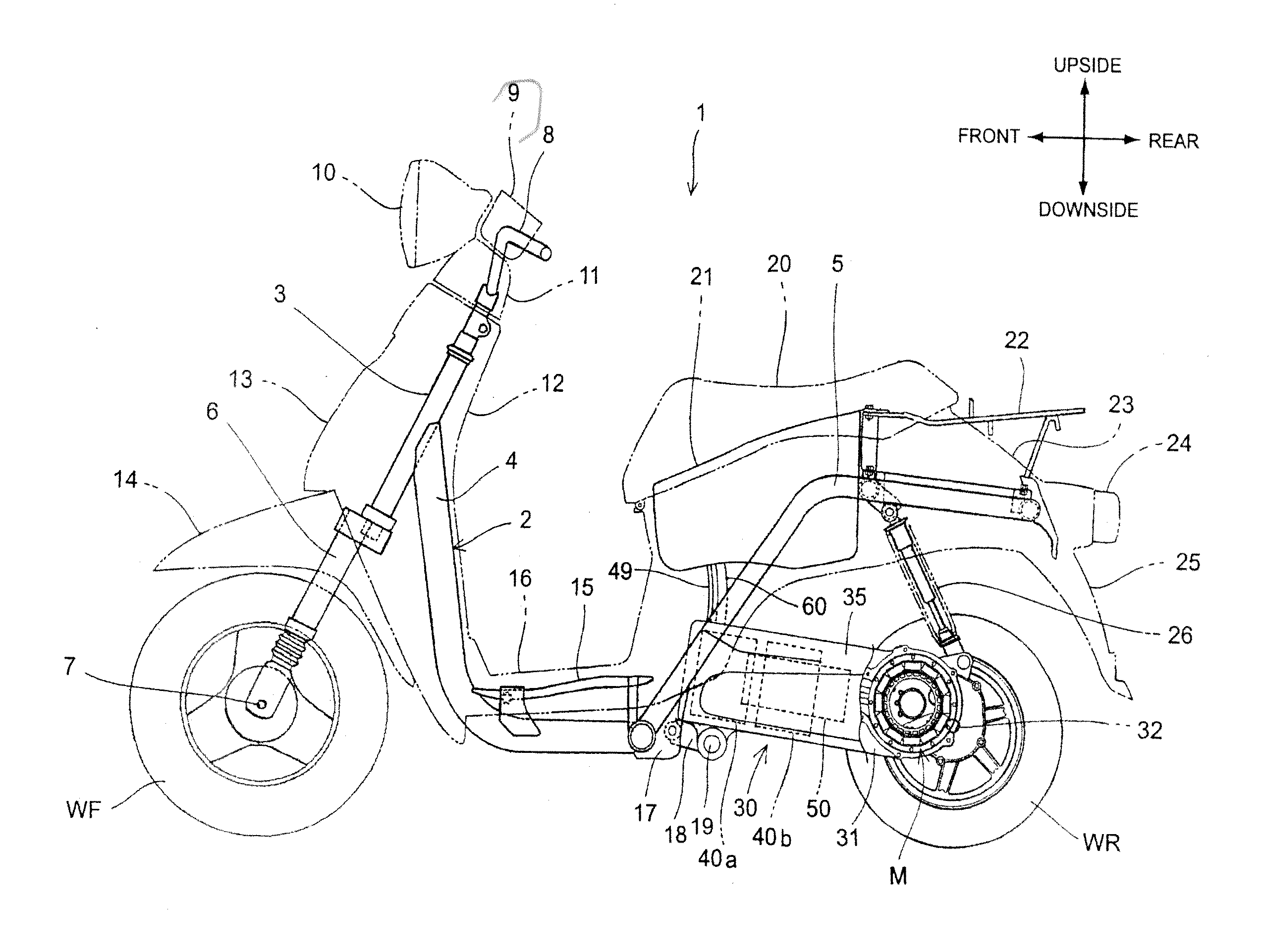
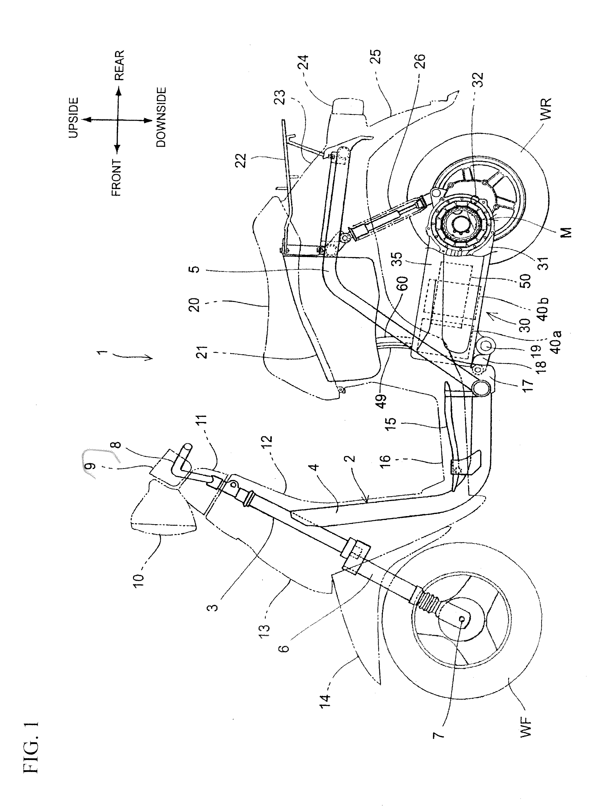
[0036]Preferred embodiments of the present invention will hereinafter be described in detail with reference to the drawings. FIG. 1 is a lateral view of a motor driven vehicle 1 according to an embodiment of the present invention. The motor driven vehicle 1 can be, for example, a scooter-type straddle-ride two-wheeled vehicle having a low-floor 16. A rear wheel WR is driven by an electric motor M housed in a swing arm (a unit swing) 30. A head pipe 3 turnably supporting a stem shaft (not shown) is connected to a front portion of the body frame 2. A steering handlebar 8 covered by a handlebar cover 11 is connected to an upper portion of the stem shaft. A pair of left and right front forks 6 is connected to a lower portion of the stem shaft. The pair of left and right front forks 6 turnably supports the front wheel WF by an axle 7.

[0037]The body frame 2 includes a main pipe 4 extending downward from the rear portion of the head pipe 3 and a rear frame 5 joined to a rear end portion of...


PUM


Abstract

A motor driven vehicle can include a swing arm swingably mounted to a vehicle body of a motor driven vehicle, and housing an electric motor driving a drive wheel of the vehicle. A pipe-like duct can have one end side connected to a hole communicating with an inside space of the swing arm, and another end side extending toward a vehicle body side. A harness, configured to drive the electric motor, can be inserted through the duct.

Description

BACKGROUND[0001]1. Field[0002]The present invention relates generally to motor driven vehicles. In particular, the invention relates to a motor driven vehicle in which the electric power of an on-board battery is supplied to an electric motor, whose drive force rotates a drive wheel for travelling.[0003]2. Description of the Related Art[0004]There has heretofore been known a motor driven vehicle in which the electric power of an on-board battery is supplied to an electric motor, whose drive force rotates a drive wheel for travelling. In such a motor driven vehicle, the electric motor, the drive circuit of the electric motor, the on-board battery and the like produce heat during travelling. Therefore, it is considered to provide an effect of cooling them in configuring a vehicle body.[0005]Patent Document 1 (Japanese Patent No. 3324192) discloses a scooter type straddle-ride motor driven two-wheeled vehicle configured as below. A swing arm is swingably mounted to a vehicle body to su...

Claims


Application Information

Patent Timeline
IPC IPC(8): B62M7/00B60K1/04B62J11/19
CPCB60L11/18B60L2200/12B62K11/10B62K25/283B62K2202/00B62M7/12B62K2208/00Y02T10/7005Y02T90/16B60R16/04B62K2204/00B60L50/60Y02T10/70B62J43/16B62J43/20B62K11/00B62M23/02B60K11/08
Inventor TANIGUCHI, YOICHIYONEHANA, ATSUSHI
Owner HONDA MOTOR CO LTD
Why Eureka
Try Eureka