Stator for electric rotating machine and method of manufacturing the same

Active Publication Date: 2012-06-28
DENSO CORP
View PDF4 Cites 9 Cited by
  • Summary
  • Abstract
  • Description
  • Claims
  • Application Information

AI Technical Summary

Benefits of technology

[0012]According to an exemplary embodiment, there is provided a stator for an electric rotating machine. The stator includes a hollow cylindrical stator core, a stator coil, an outer cylinder, and at least one restraint. The stator core is comprised of a plurality of stator core segments that are arranged in the circumferential direction of the stator core to adjoin one another in the circumferential direction. The stator coil is mounted on the stator core. The outer cylinder is fitted on the radially outer surfaces of the stator core segments so as to fasten the stator core segments together. The restraint is arranged on an axial side of the stator core and retained by the outer cylinder so as to restrain axial deformation of the stator core segments due to the fastening force of the outer cylinder.
[0013]Consequently, even when there are variations in the dimensions of the outer cylinder and the stator core segments and thus the circumferential compressive stress induced by the fastening force of the outer cylinder in the stator core segments is excessively large, it is still possible to effectively restrain, with the at least one restraint, the axial deformation of the stator core segments due to the circumferential compressive stress. As a result, it is possible to reliably prevent buckling of the magnetic steel sheets that form the stator core segments

Problems solved by technology

However, with the above method, buckling of the magnetic steel sheets that are laminated to form the stator core segments may occur when there are variations in the dimensions of the magnet

Method used


Image

  • Stator for electric rotating machine and method of manufacturing the same
  • Stator for electric rotating machine and method of manufacturing the same
  • Stator for electric rotating machine and method of manufacturing the same

Examples


first embodiment

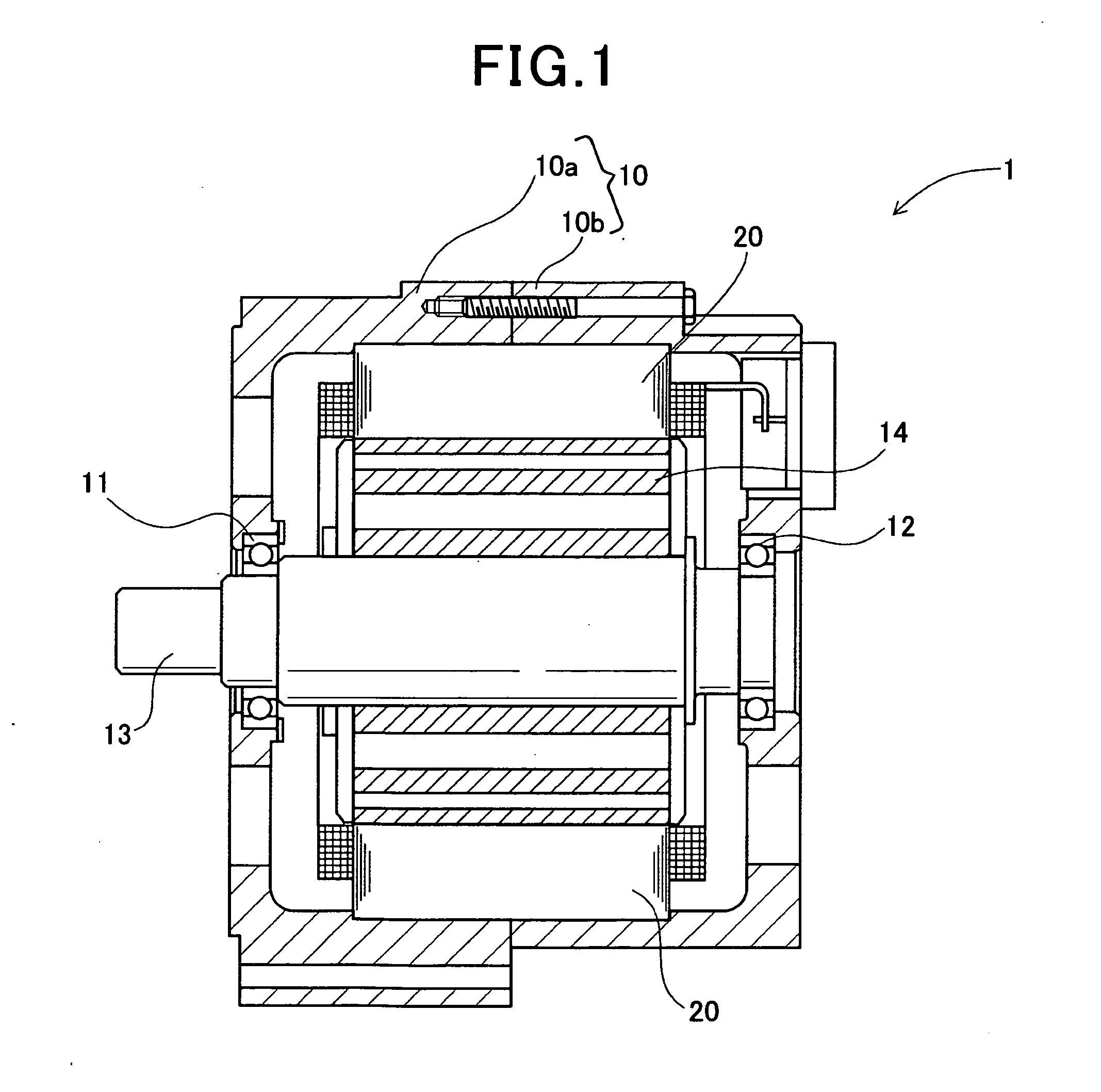
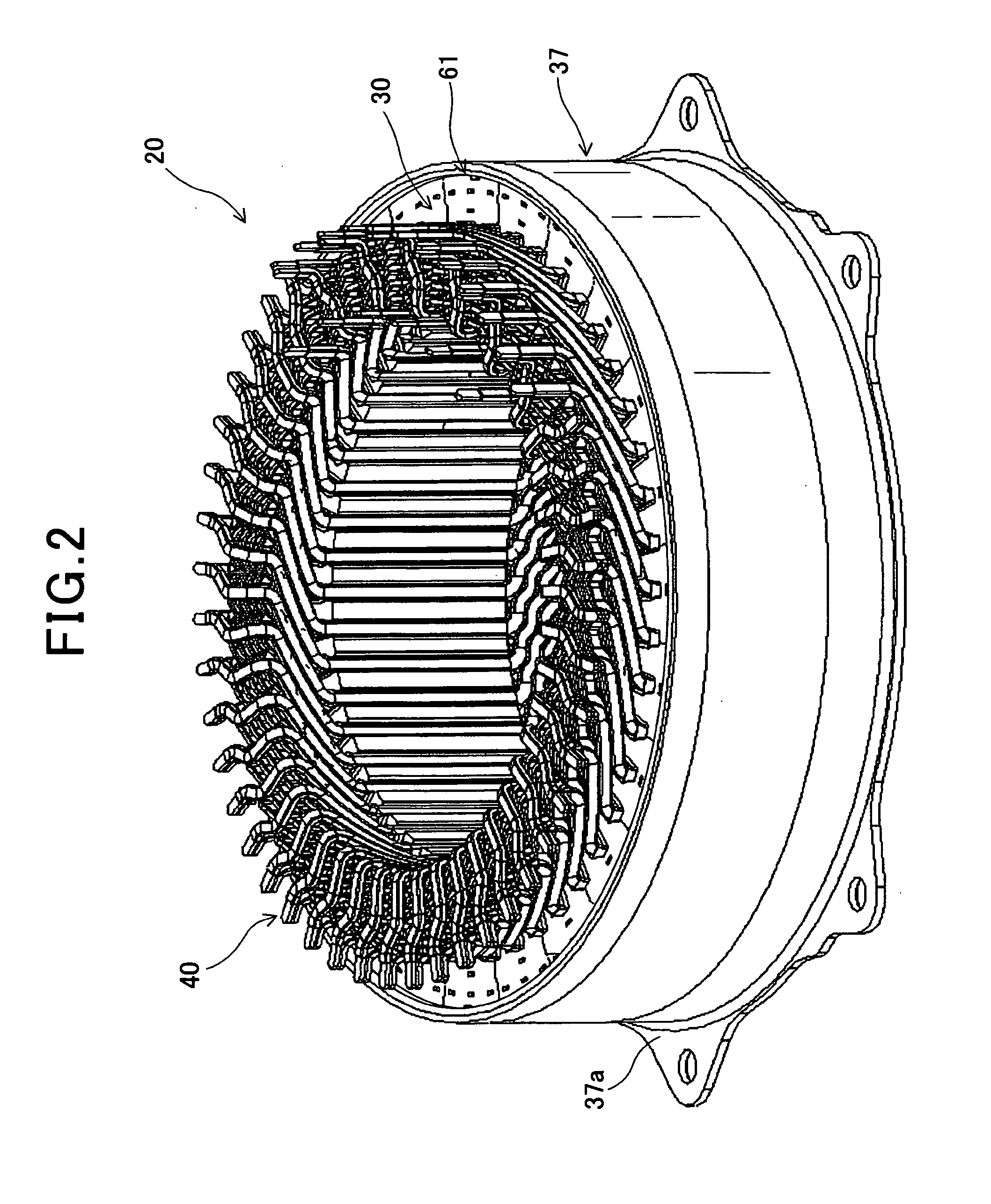
[0031]FIG. 1 shows the overall configuration of an electric rotating machine 1 which includes a stator 20 according to a first embodiment.

[0032]The electric rotating machine 1 is designed to be used in a motor vehicle, such as an electric vehicle or a hybrid vehicle, and can function both as an electric motor and as an electric generator.

[0033]As shown in FIG. 1, the electric rotating machine 1 further includes a housing 10 and a rotor 14 in addition to the stator 20. The housing 10 is comprised of a pair of cup-shaped housing pieces 10a and 10b which are jointed together at the open ends thereof The housing 10 has a pair of bearings 11 and 12 mounted therein, via which a rotating shaft 13 is rotatably supported by the housing 10. The rotor 14 is received in the housing 10 and fixed on the rotating shaft 13. The stator 20 is fixed in the housing 10 so as to surround the radially outer periphery of the rotor 14.

[0034]The rotor 14 includes a plurality of permanent magnets that form a ...

second embodiment

[0086]This embodiment illustrates a stator 20 which has almost the same structure as the stator 20 according to the first embodiment; accordingly, only the differences therebetween will be described hereinafter.

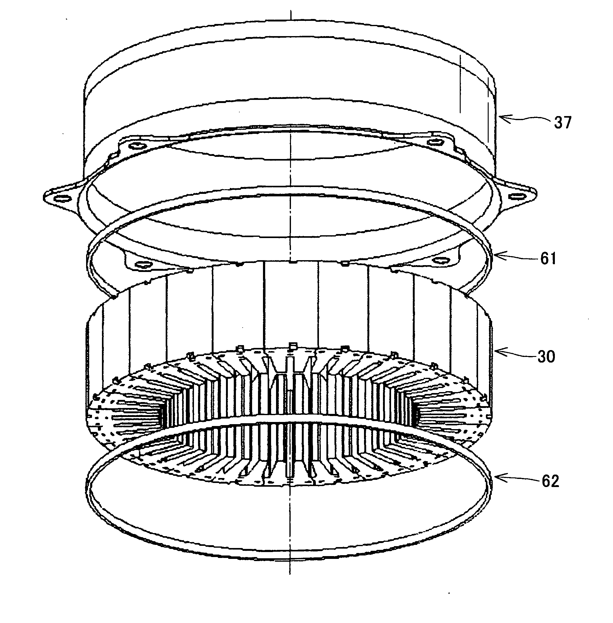
[0087]In the first embodiment, the stator 20 includes the pair of restraints 61 and 62 each of which is formed as an independent part and assembled into the stator 20. More specifically, the restraints 61 and 62 are respectively joined to the axial end faces of the stator core 30 and both shrink-fitted to the outer cylinder 37.

[0088]In comparison, in the present embodiment, as shown in FIGS. 9-11, the stator 20 includes a pair of restraints 61A and 62 that are respectively arranged on opposite axial sides of the stator core 30. Further, the stator 20 includes an outer cylinder 38 instead of the outer cylinder 37 in the first embodiment.

[0089]The restraint 62 is identical to that in the first embodiment. That is, the restraint 62 is formed as an independent part, joined to one...


PUM


Abstract

A stator for an electric rotating machine includes a hollow cylindrical stator core, a stator coil, an outer cylinder, and at least one restraint. The stator core is comprised of a plurality of stator core segments that are arranged in the circumferential direction of the stator core to adjoin one another in the circumferential direction. The stator coil is mounted on the stator core. The outer cylinder is fitted on the radially outer surfaces of the stator core segments so as to fasten the stator core segments together. The restraint is arranged on an axial side of the stator core and retained by the outer cylinder so as to restrain axial deformation of the stator core segments due to the fastening force of the outer cylinder.

Description

CROSS-REFERENCE TO RELATED APPLICATION[0001]This application is based on and claims priority from Japanese Patent Application No. 2010-293587, filed on Dec. 28, 2010, the content of which is hereby incorporated by reference in its entirety into this application.BACKGROUND[0002]1. Technical Field[0003]The present invention relates to stators for electric rotating machines that are used in, for example, motor vehicles as electric motors and electric generators, and to methods of manufacturing the stators.[0004]2. Description of Related Art[0005]Conventionally, there are known stators for electric rotating machines which include a hollow cylindrical stator core, a stator coil, and an outer cylinder.[0006]The stator core is comprised of a plurality of stator core segments that are arranged in the circumferential direction of the stator core to adjoin one another in the circumferential direction. Further, to reduce iron loss of the stator core, each of the stator core segments is formed ...

Claims


Application Information

Patent Timeline
IPC IPC(8): H02K1/06
CPCH02K1/185H02K1/148
Inventor IKUTA, HIROYUKIISHIZUKA, ATSUO
Owner DENSO CORP
Why Eureka
Try Eureka