
Electromagnetic wave reverberation chamber

Active Publication Date: 2012-06-28
ELECTRONICS & TELECOMM RES INST
View PDF7 Cites 22 Cited by
  • Summary
  • Abstract
  • Description
  • Claims
  • Application Information

AI Technical Summary

Benefits of technology

[0015]In view of the above, the present invention provides an electromagnetic wave reverberation chamber including a small a

Problems solved by technology

However, the effect of the electromagnetic wave generated by the device to a human body has been being an important issue as the use of the portable device is increased.
However, it has been being reported that the electromagnetic can affect various diseases such as a leukemia, an encephaloma, a headache, a decreased visual acuity, a brain wave disorder when the electromagnetic wave is accumulated in the human body, the damage of the reproduction ability of a man, etc.
In addition, a malfunction between information communication devices due to undesirable electromagnetic wave is constantly reported.
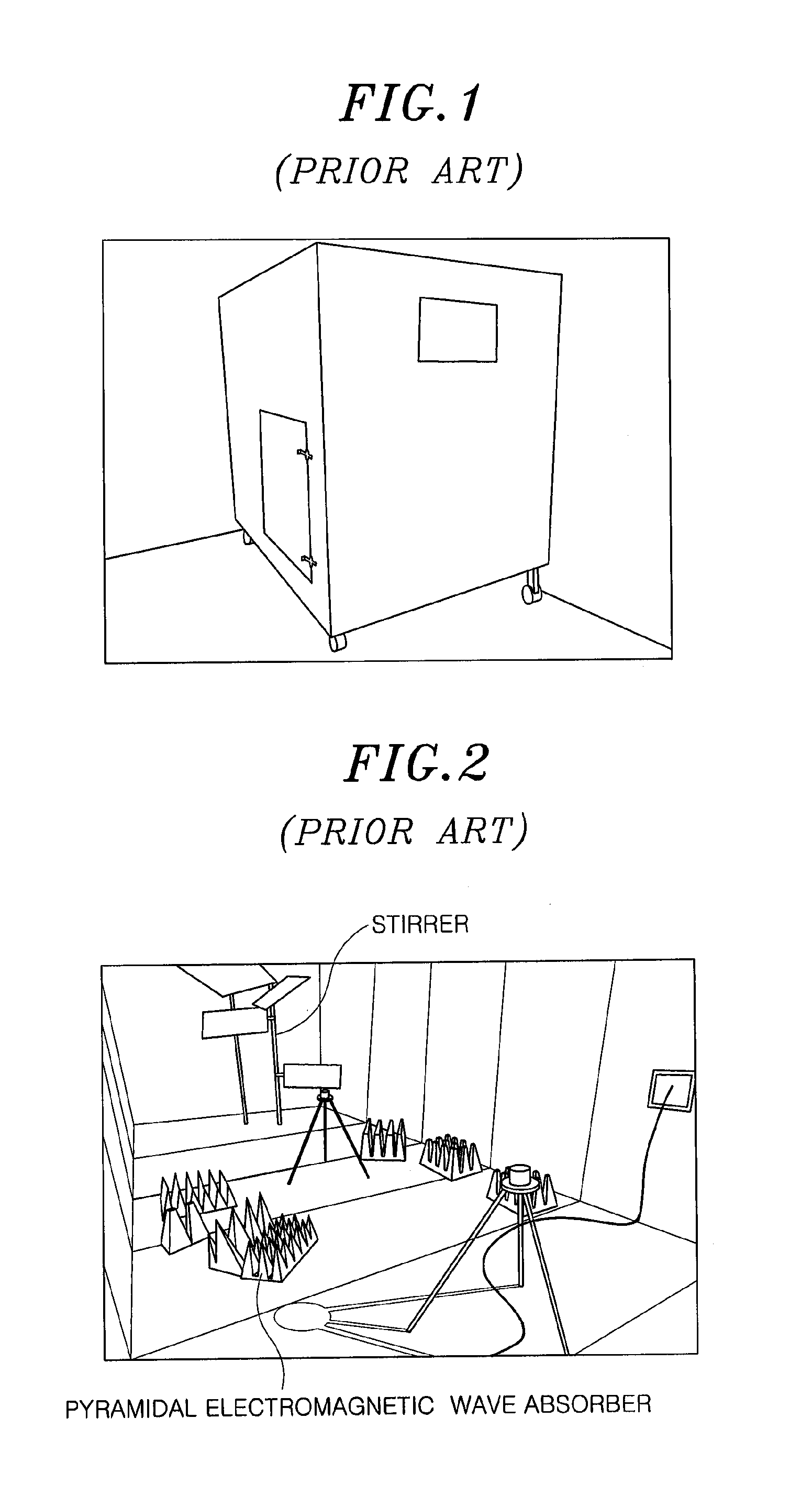
However, the conventional pyramidal electromagnetic wave absorber is not suitable for a device to be tested since the size of the conventional pyramidal electromagnetic wave absorber is so large that the inside space of the chamber can be small.
In this case, since the electromagnetic wave reverberation chamber should be manufactured to be larger, there exist problems that the manufacture cost of the electromagnetic wave reverberation chamber is raised and an installation space for the chamber should be larger.
In addition, since the conventional pyramidal electromagnetic wave absorber is manufactured by using a material having absorption characteristic and is developed by a trial and error method, there exist considerable problems that the manufacturing process of the absorber is complicated and it is difficult to adjust the absorption characteristic and a absorption frequency bandwidth.
However, the conventional resonant absorber has a problem that the thickness of the dielectric spacer should be equal to or larger than 4 / λ from the metal conductor ground surface.

Method used


Image

  • Electromagnetic wave reverberation chamber
  • Electromagnetic wave reverberation chamber
  • Electromagnetic wave reverberation chamber

Examples


Embodiment Construction

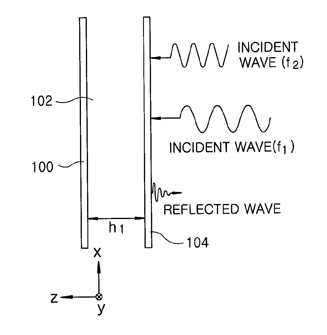
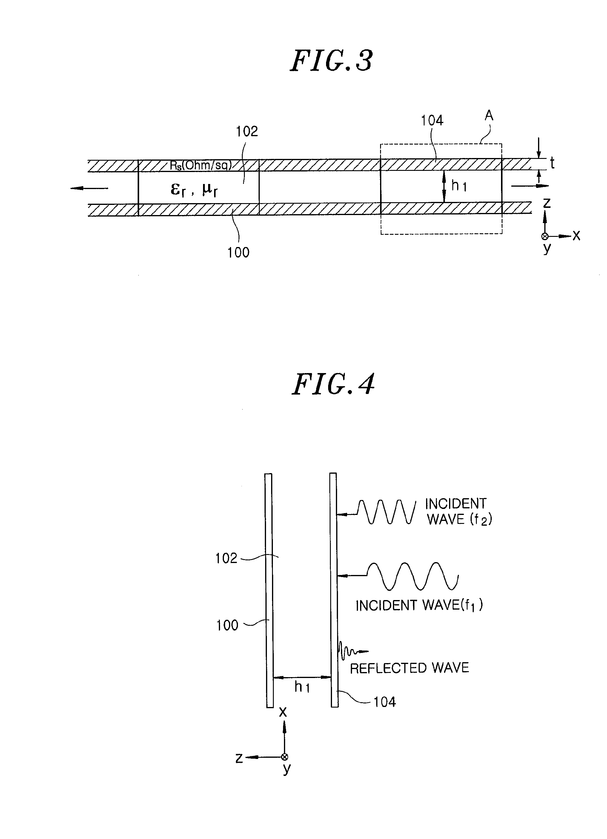
[0034]The present invention provides an electromagnetic wave reverberation chamber including an electromagnetic wave absorbing apparatus to which a periodic structure technology such as an electromagnetic bandgap (EBG) is applied.

[0035]The electromagnetic bandgap as a technique of employing a periodic structure may be implemented by periodically arranging specifically designed unit cell patterns on a typical electric conductor at regular intervals. Since a tangential component of a magnetic field at a particular band on the surface of the electromagnetic bandgap becomes zero, the electromagnetic bandgap has the characteristic of preventing current from flowing through the surface. Such an electromagnetic bandgap may be regarded as a magnetic conductor opposite to the typical electric conductor. The surface of the electromagnetic bandgap is a high-impedance surface (HIS) in configuration of a circuit.

[0036]The frequency response characteristics of the electromagnetic bandgap may be c...


PUM


Abstract

An electromagnetic wave reverberation chamber includes: an electromagnetic wave absorbing apparatus installed in an intended space of the electromagnetic wave reverberation chamber for adjusting a reflection characteristic of an inside of the electromagnetic wave reverberation chamber, wherein the electromagnetic wave absorbing apparatus have an electromagnetic bandgap structure including a plurality of unit cells arranged periodically.

Description

CROSS-REFERENCE(S) TO RELATED APPLICATION(S)[0001]The present invention claims priority of Korean Patent Application No. 10-2010-0133406, filed on Dec. 23, 2010, which is incorporated herein by reference.FIELD OF THE INVENTION[0002]The present invention relates to an electromagnetic wave reverberation chamber; and more particularly, to an electromagnetic wave reverberation chamber including an electromagnetic wave absorbing apparatus to which a periodic structure technology such as an electromagnetic bandgap (EBG) is applied.BACKGROUND OF THE INVENTION[0003]As information technology is developed rapidly and a desire for the communication of a human being is increased, mobile communication devices such as a portable device are necessities of a contemporary man. However, the effect of the electromagnetic wave generated by the device to a human body has been being an important issue as the use of the portable device is increased. At present, a relation between the electromagnetic wave ...

Claims


Application Information

Patent Timeline
IPC IPC(8): H01Q17/00
CPCH01Q15/0013G01R29/0821H01Q17/008G01R29/0814H01Q15/006
Inventor SIM, DONG-UK
Owner ELECTRONICS & TELECOMM RES INST
Learn More