
Recording apparatus

Active Publication Date: 2012-06-28
SEIKO EPSON CORP
View PDF7 Cites 9 Cited by
  • Summary
  • Abstract
  • Description
  • Claims
  • Application Information

AI Technical Summary

Benefits of technology

[0008]An advantage of some aspects of the invention is to provide a low power recording apparatus having a superior thermal responsiveness.
[0010]According to the configuration, the supporting member having a surface treatment layer having a radiation factor of 0.85 or more on the supporting surface supporting the recording medium is heated. When the supporting member is a heat-receiving side, heat storage effect is achieved in the surface treatment layer due to heat absorption, contributing to a reduction in start-up time and power savings. On the contrary, when the supporting member is a heat-discharging side, heat discharging performance is increased by the radiation factor of the surface treatment layer and thermal responsiveness is improved.
[0012]According to the configuration, since the radiation heating unit is disposed opposite to the surface treatment layer, it is possible to radiation-heat the surface treatment layer of the supporting member and also to directly heat the recording medium, thereby reducing energy loss.
[0014]According to another aspect of the invention, absorption efficiency of infrared energy in water molecules is increased and radiation heating is implemented with a wavelength which includes a region of 2 to 4 μm at the main portion of a peak of a radiation spectrum, such that it is possible to vibrate the water molecules contained in the fluid, such as ink, and rapidly encourage drying due to the friction heat, without significantly increasing the temperature of the peripheral members which do not contain water molecules.
[0020]According to still another aspect of the invention, since the recording head is disposed at the same side as the radiation heating unit, it is possible to prevent the fluid ejecting unit from being heated and the fluid from thickening and sticking.

Problems solved by technology

However, the section in JP-A-2000-225696 does not directly supply infrared energy onto the recording surface of a recording medium, such that energy loss occurs and the ink may solidify and adhere to the nozzle due to radiation of the infrared energy to the nozzle plate that is ink ejecting portion.
Further, in the section in JP-A-2000-225696, thermal responsiveness is poor particularly at the infrared reflecting member, a large amount of power is necessary to increase the temperature to a predetermined level, and it takes time for the heat to dissipate after being used.

Method used


Image

  • Recording apparatus
  • Recording apparatus
  • Recording apparatus

Examples


Embodiment Construction

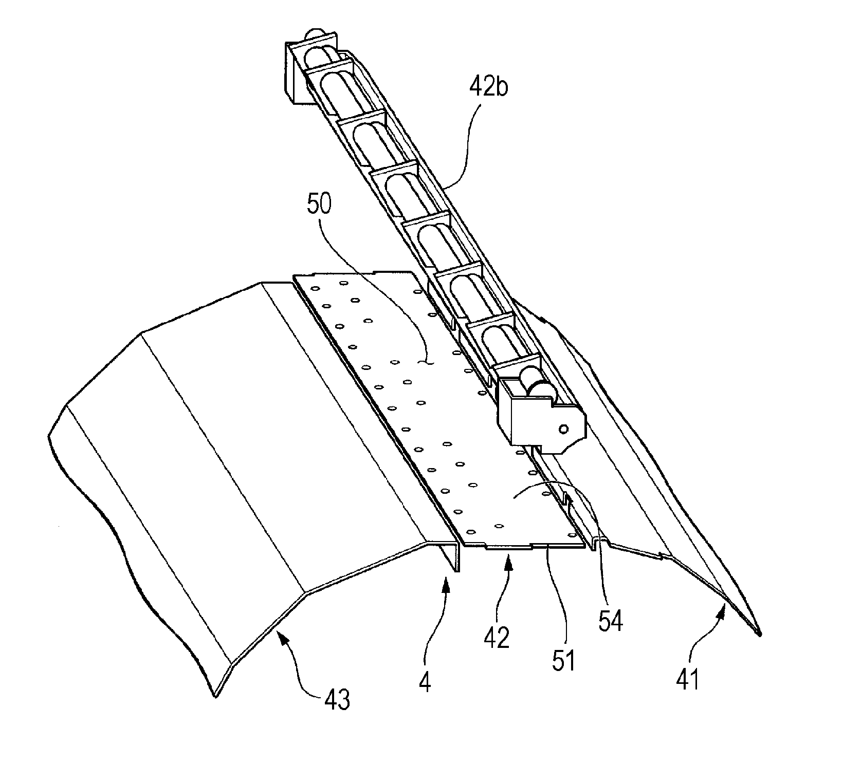
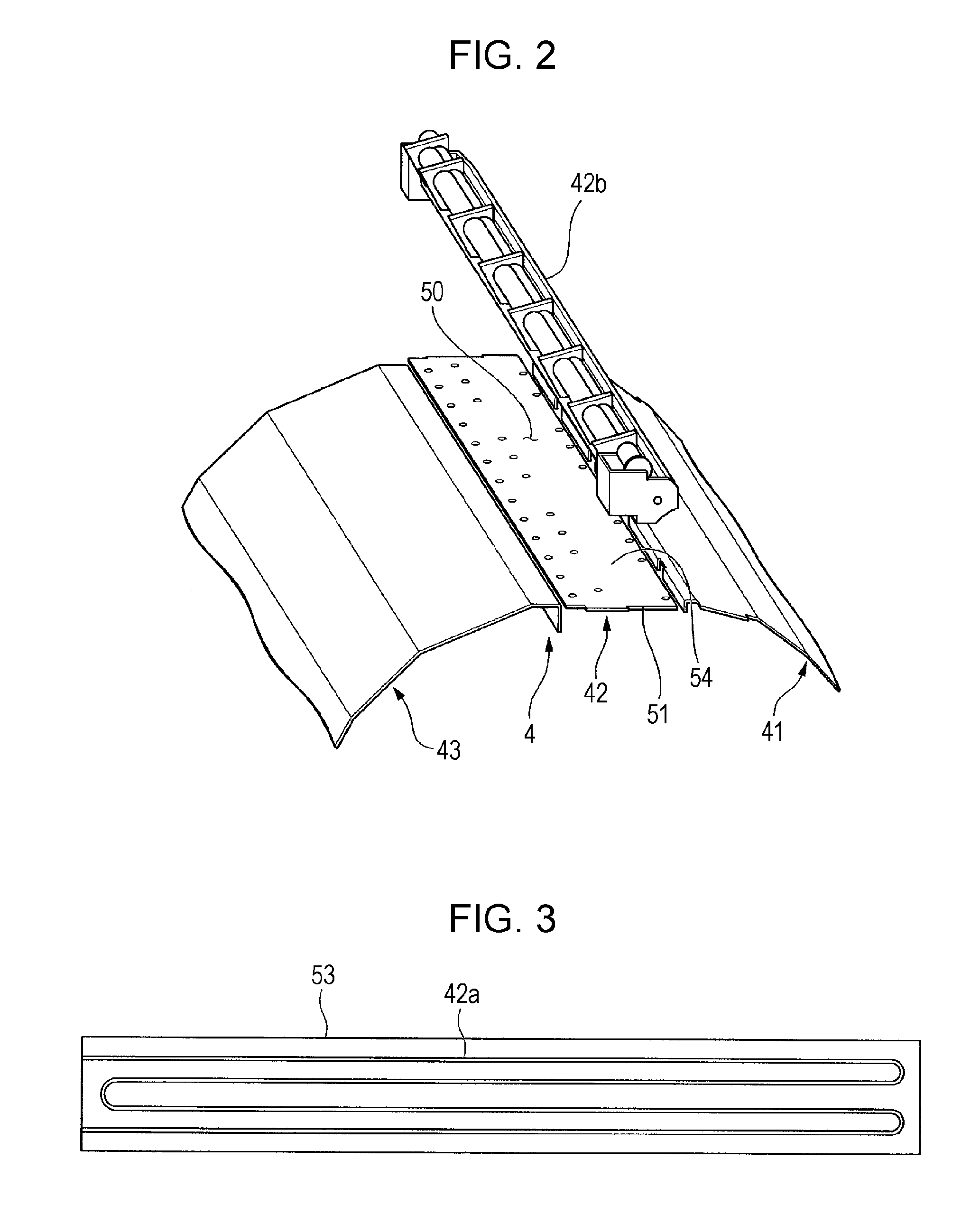
[0027]Embodiments of a recording apparatus of the invention are described with reference to the drawings. Further, the scales of the members are appropriately changed such that the members can be recognized in the drawings used for the following description. An ink jet type printer (hereafter, simply referred to as a printer) is exemplified in the embodiment as a recording apparatus of the invention.

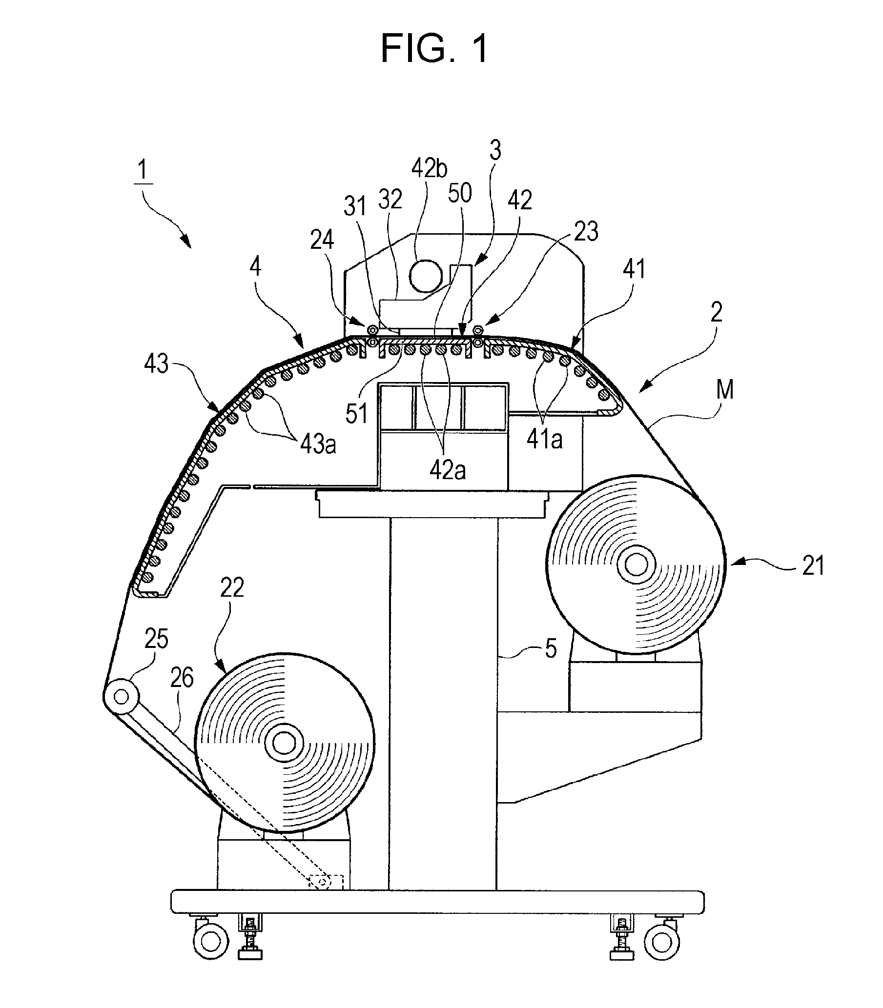
[0028]FIG. 1 is a view showing the configuration of a printer 1 according to an embodiment of the invention.

[0029]The printer 1 is a large format printer (LFP) handling relatively large media (recording media) M. The medium M of the embodiment is implemented by a vinyl chloride series having a width of, for example, 64 inches.

[0030]As shown in FIG. 1, the printer 1 includes a transporting unit (transporting device) 2 that transports the medium M in a roll-to-roll method, a recording unit 3 that records images or characters by ejecting ink (fluid) onto the medium M, and a heating unit (he...


PUM


Abstract

A recording apparatus includes: a recording head that ejects fluid onto a recording medium; a supporting member that supports the recording medium; and a heating device that heats the supporting member, in which a supporting surface that supports the recording medium in the supporting member has a surface treatment layer having a radiation factor of 0.85 or more.

Description

[0001]The entire disclosure of Japanese Patent Application No: 2010-288114, filed Dec. 24, 2010 is expressly incorporated by reference herein in its entirety.BACKGROUND[0002]1. Technical Field[0003]The present invention relates to a recording apparatus.[0004]2. Related Art[0005]An ink jet printer is known as a type of recording apparatus that records images or characters by ejecting fluid onto a recording medium. In the ink jet printer, when ink (fluid) that needs permeation drying or evaporation drying is used, there is need for a heating device to be provided to dry the ink ejected on the recording medium.[0006]An ink jet recording apparatus disclosed in JP-A-2000-225696 is known as such a recording apparatus. The ink jet recording apparatus employs a section equipped with an infrared heater to heat the rear side of the recording surface of a recording medium and an infrared reflecting member at a position opposite to the infrared heater, and indirectly supplies infrared energy to...

Claims


Application Information

Patent Timeline
IPC IPC(8): B41J2/01
CPCB41J11/06B41J11/002B41J11/00244B41J11/00216
Inventor SASAKI, TSUNEYUKI
Owner SEIKO EPSON CORP
Learn More