Resin coated optical fiber
a technology of optical fibers and coatings, applied in the field of resin coated optical fibers, can solve problems such as difficult compatibility with each other, and achieve the effects of suppressing the increase of transmission loss, excellent long-term reliability, and suppressing the fracture of glass optical fibers
- Summary
- Abstract
- Description
- Claims
- Application Information
AI Technical Summary
Benefits of technology
Problems solved by technology
Method used
Image

Examples
example 1
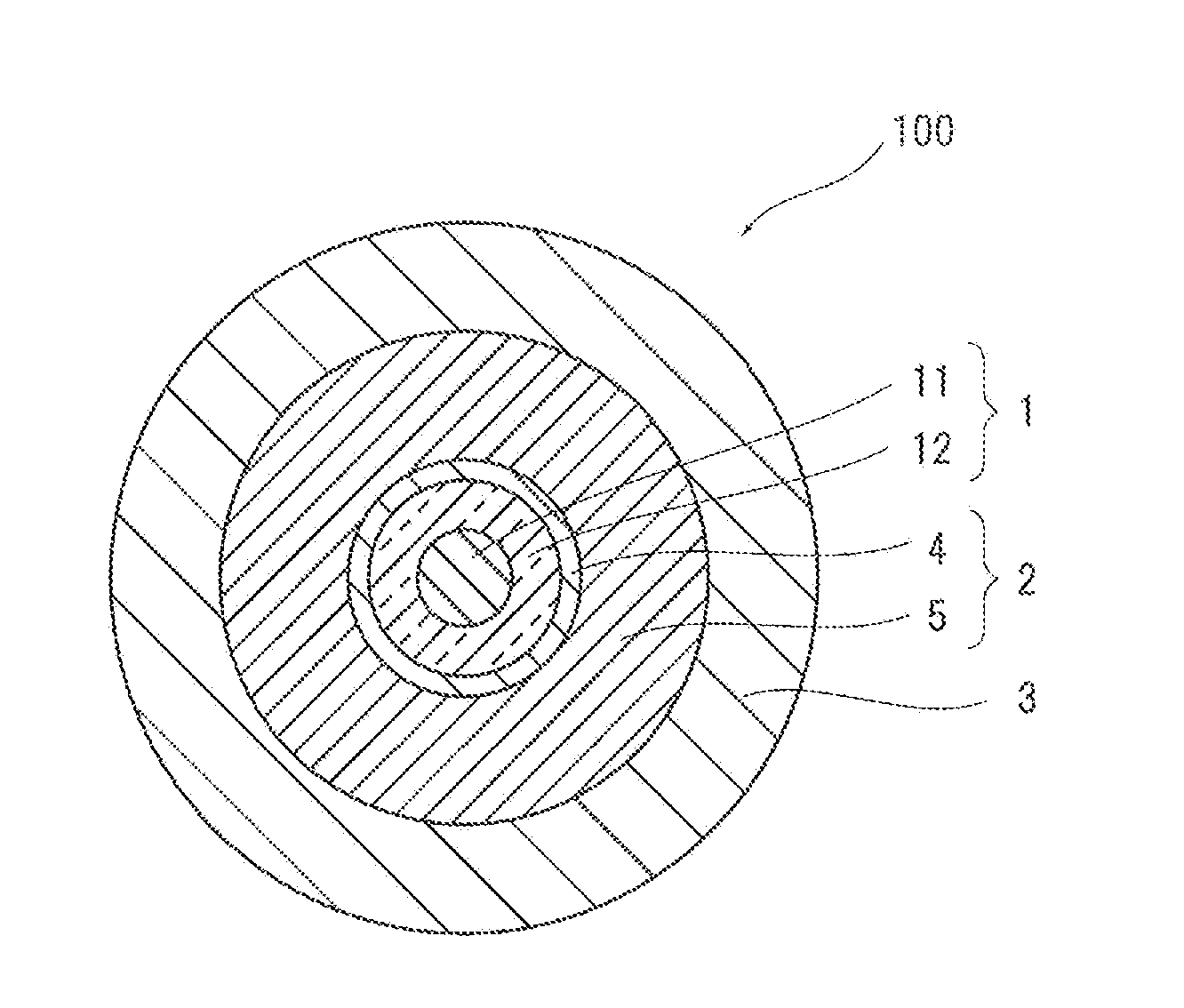
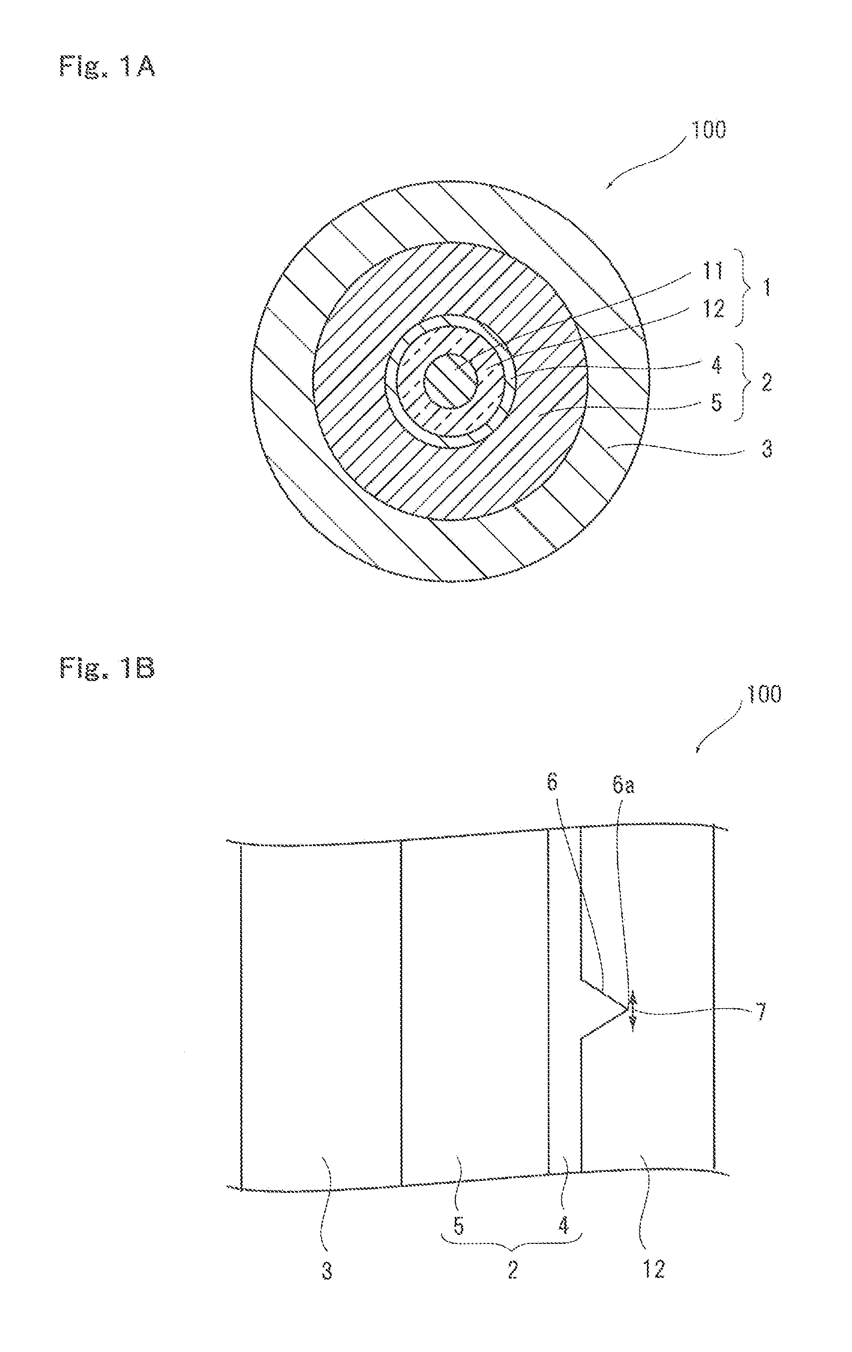
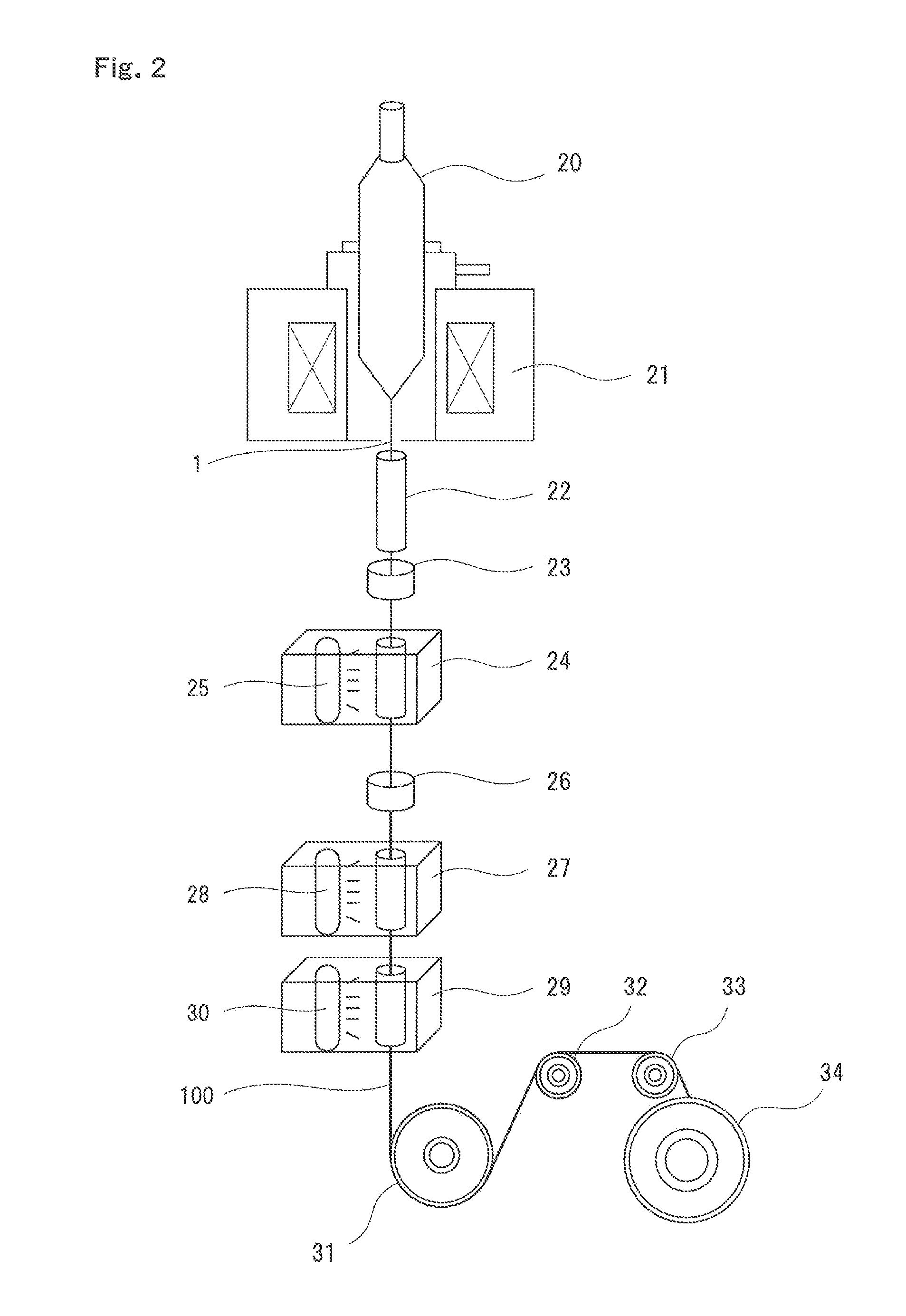
[0056]In example 1, first, a glass optical fiber with an outer diameter of 125 μm was formed by heating and drawing a preform, being a base material of the glass optical fiber having a core portion and a cladding portion, by using a drawing device shown in FIG. 2. At this time, the glass optical fiber was cooled to a room temperature from a high temperature, and therefore roughness was formed on the surface of the glass optical fiber. Next, an inner layer with a thickness of 10 μm (Young's modulus at room temperature: 1.2 MPa) and an outer layer (Young's modulus: 0.5 MPa) were formed on the surface of the obtained glass optical fiber, so that an outer diameter of the primary layer composed of the inner layer and the outer layer was set to 187.5 μm. Then, a secondary layer (Young's modulus: 600 MPa) was formed on the surface of the outer layer of the primary layer, to thereby obtain a resin coated optical fiber according to the example 1 with an outer diameter of 250 μm. An ultraviol...
examples 2 to 4
, Comparative Examples 2, 3
[0071]The resin coated optical fiber of examples 2 to 4, comparative example 2, and comparative example 3 is respectively formed almost similarly to the example 1 and the comparative example 1 (A different point between the example 1 and the comparative example 1 will be described hereafter), and the same evaluation as described above was performed. Evaluation results are summarized in the table 1, together with the example 1 and the comparative example 1. Each case will be described hereafter.
example 2
[0072]According to the example 2, a different point from the example 1 is simply that the Young's modulus of the secondary layer is changed to 1200 MPa, and the other structure is formed similarly to the example 1. As shown in the table 1, according to the example 2, the long-term reliability is excellent even after the accelerated deterioration test is carried out in the same way as the example 1, and the micro bending loss and the increase of transmission loss by cabling are suppressed to be sufficiently small.
PUM
| Property | Measurement | Unit |
|---|---|---|
| Young's modulus | aaaaa | aaaaa |
| Young's modulus | aaaaa | aaaaa |
| Young's modulus | aaaaa | aaaaa |
Abstract
Description
Claims
Application Information
 - R&D
- Intellectual Property
- Life Sciences
- Materials
- Tech Scout
- Unparalleled Data Quality
- Higher Quality Content
- 60% Fewer Hallucinations
Browse by: Latest US Patents, China's latest patents, Technical Efficacy Thesaurus, Application Domain, Technology Topic, Popular Technical Reports.
© 2025 PatSnap. All rights reserved.Legal|Privacy policy|Modern Slavery Act Transparency Statement|Sitemap|About US| Contact US: help@patsnap.com