Thermal displacement correcting apparatus and method for a machine tool

a technology of thermal displacement correction and machine tool, which is applied in the direction of computer control, program control, instruments, etc., can solve the problems of thermal deformation in the machine tool, parameter preparation, and increase of malfunction from incorrectly set parameters, so as to achieve excellent productivity and manageability of the thermal displacement correction apparatus and method

Active Publication Date: 2012-06-28
OKUMA CORP
View PDF19 Cites 12 Cited by
  • Summary
  • Abstract
  • Description
  • Claims
  • Application Information

AI Technical Summary

Benefits of technology

[0007]Therefore, it is an object of the invention according to first to fourth aspects to provide a thermal displacement correcting apparatus or method for a machine tool, that enables setting and operating to be performed accurately and easily, even if there are a large number of sets of specifications.
[0012]According to the present invention, temperature sensors and parameters corresponding to estimated elements relating to the set of specifications of a machine tool for which a correction is to be made, are selected from a database based on machine information. As a result, even if there are a plurality of sets of specifications, it is sufficient to simply prepare a common database, so productivity (ease of formulation) and manageability of the thermal displacement correcting apparatus and method become extremely good.

Problems solved by technology

The transfer of heat generated at power portions and slide portions and the like and a change in environment temperature cause thermal deformation in a machine tool.
When this kind of thermal displacement correcting apparatus is applied to machines of the same model but with different specifications, the parameters must be prepared for each, which is tedious.
As the number of sets of specifications increases, it becomes more tedious to set the parameters and operate the various parameter files, and the risk of a malfunction from an incorrectly set parameter increases, such that productivity and manageability of the thermal displacement correcting apparatus become poor.

Method used


Image

  • Thermal displacement correcting apparatus and method for a machine tool
  • Thermal displacement correcting apparatus and method for a machine tool
  • Thermal displacement correcting apparatus and method for a machine tool

Examples


first example embodiment

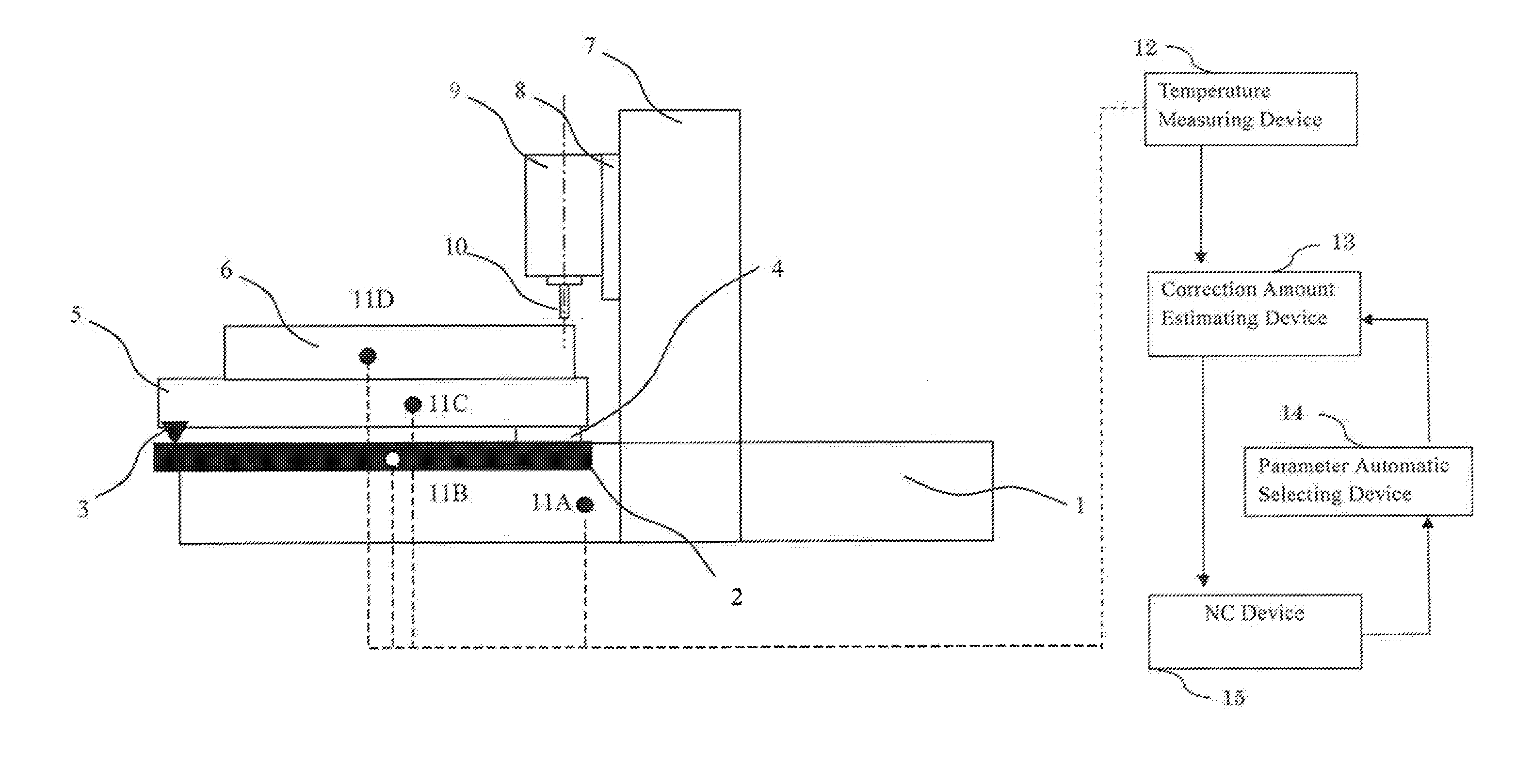
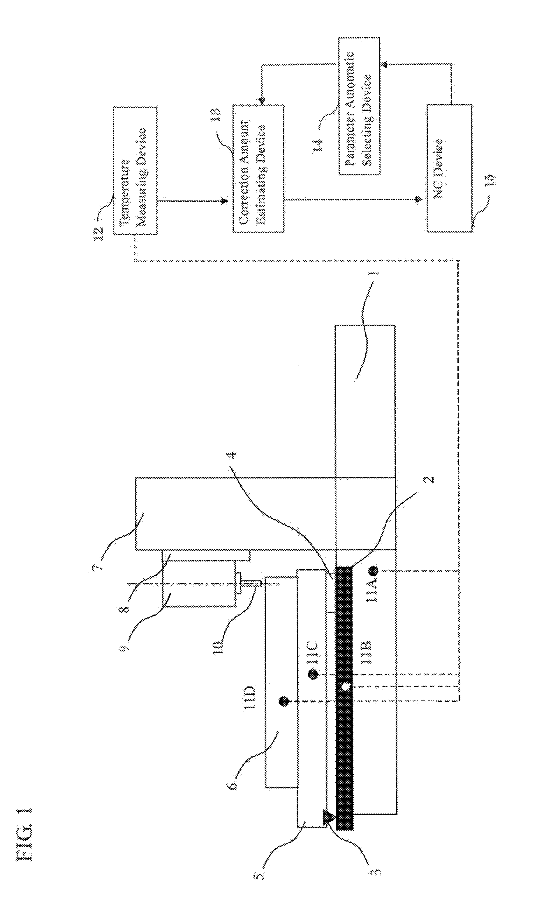
[0022]FIG. 1 is a side view of a machine tool (a portal machining center) to which a thermal displacement correcting apparatus according to a first example embodiment of the present invention has been applied. A bed 1 is arranged along an X-axis (i.e., an axis in the left-right direction in FIG. 1; the right is positive). A table 5 on which a workpiece 6 is able to be mounted is supported so as to be able to move in the direction of the X-axis on the bed 1 via a nut 4.

[0023]A column 7 stands on both side surfaces of the bed 1, and a cross rail (not shown) is fixed between the columns 7. A saddle 8 is supported so as to be able to move in the direction of a Y-axis (i.e., an axis in the direction perpendicular to the surface of the paper in FIG. 1; the near side is positive) on the cross rail. Furthermore, a main spindle 9 is supported, so as to be able to move in the direction of a Z-axis (i.e., an axis in the vertical direction of FIG. 1; up is positive), on the saddle 8, and a tool...

second example embodiment

[0043]FIG. 5 is a side view of a machine tool (standard specifications) to which a thermal displacement correcting apparatus according to a second example embodiment of the present invention has been applied. A headstock 103 is arranged on a bed 102 on a leg 101. The headstock 103 rotatably supports a main spindle 104 that has a chuck (not shown) that holds a workpiece. Also, a saddle 105 is arranged so as to be able to move in the axial direction of the main spindle 104 (i.e., in the direction perpendicular to the surface of the paper on which FIG. 5 is drawn) on the bed 102, a tool rest 106 is supported so as to be able to move in the radial direction of the main spindle on the saddle 105, and a turret 108 that holds a tool 107 is provided on the tool rest 106.

[0044]Further, temperature sensors ch1 to ch4 are arranged on the bed 102, the headstock 103, the saddle 105, and the tool rest 106, respectively. A temperature measuring device 109 that converts analog signals output from t...

modified example

[0054]Another example embodiment of the present invention created mainly by changing the example embodiment described above will now be illustrated.

[0055]When estimating the thermal displacement according to the first example embodiment, the detected temperatures of the temperature sensors may be estimated temperatures expressed by [Expression 7] below. Here, Oi, t is the estimated temperature of the estimated element i, Oi, t-1 is the estimated temperature of the estimated element i at the time of the last calculation (and is stored in appropriate storing means), Ti, t is the detected temperature of the estimated element i, b is the time interval of the calculations, and βi is the constant at the time of displacement of the estimated element i. Also, βi is linked to the machine information, and is automatically selected as a parameter based on the machine information. Using the estimated temperatures in this way makes it possible to make a highly accurate correction based on the th...


PUM


Abstract

A thermal displacement correcting apparatus includes a correction amount estimating device and a parameter automatic selecting device that, in a machine tool having two different sets of specifications that differ due to the presence / absence of a scale and different methods of measuring the lengths of a bed and a table, estimate a thermal displacement correction amount of the machine tool of each set of specifications. The two devices store a collection of parameters for an estimated thermal displacement calculation corresponding to each of the bed, the scale, the table, and a workpiece, as a database, and select the parameters belonging to the set of specifications from the database based on machine information according to each set of specifications, calculate estimated thermal displacements of the bed, the table, and the workpiece, or also the scale, according to the selected parameters, and combine the estimated thermal displacements.

Description

[0001]This application claims the benefit of Japanese Patent Application Number 2010-292026 filed on Dec. 28, 2010, the entirety of which is incorporated by reference.BACKGROUND OF THE INVENTION[0002]1. Technical Field[0003]The present invention relates to a thermal displacement correcting apparatus and a thermal displacement correcting method for a machine tool such as a NC lathe and a machining center.[0004]2. Background Art[0005]The transfer of heat generated at power portions and slide portions and the like and a change in environment temperature cause thermal deformation in a machine tool. Because this thermal deformation affects the machining accuracy, an apparatus has been proposed that estimates the amount of thermal deformation from the machine body temperature and makes corrections when machining (for example, the apparatus described in Japanese Patent Application Publication No. JP-A-2006-281335). This thermal displacement correcting apparatus estimates and corrects therm...

Claims


Application Information

Patent Timeline
Patent Type & Authority Applications(United States)
IPC IPC(8): G05B19/404
CPCB23Q11/0007G05B2219/49209G05B19/404
Inventor MURAHASHI, TOSHIHIKOFUNAGUCHI, HIRONORI
Owner OKUMA CORP
Why Eureka
Try Eureka