Padlock

Active Publication Date: 2012-07-05
ABUS AUGUST BREMICKER SOEHNE AG
View PDF5 Cites 9 Cited by
  • Summary
  • Abstract
  • Description
  • Claims
  • Application Information

AI Technical Summary

Benefits of technology

[0019]To achieve a clearance-free fit of the inner housing in the outer housing without additional fastening measures, it is furthermore of advantage if the named front wall section of the outer housing has a recess into which the front insertion part engages in shape matched manner and if the named rear wall section of the outer housing has a recess into which the rear insertion part engages in shape matched manner. The inner housing can hereby be fixed in a lateral direction relative to the outer housing, with simultaneously a centering being able to be achieved if suitable centering chamfers are formed at the named recesses.
[0020]In accordance with an advantageous

Problems solved by technology

The assembly of such a padlock is, however, undesirably complex and/or expensive.
A self-centering of the inner housing can even be achieved by corresponding mold inclinations so that ultimately a higher f

Method used


Image

  • Padlock
  • Padlock
  • Padlock

Examples


Embodiment Construction

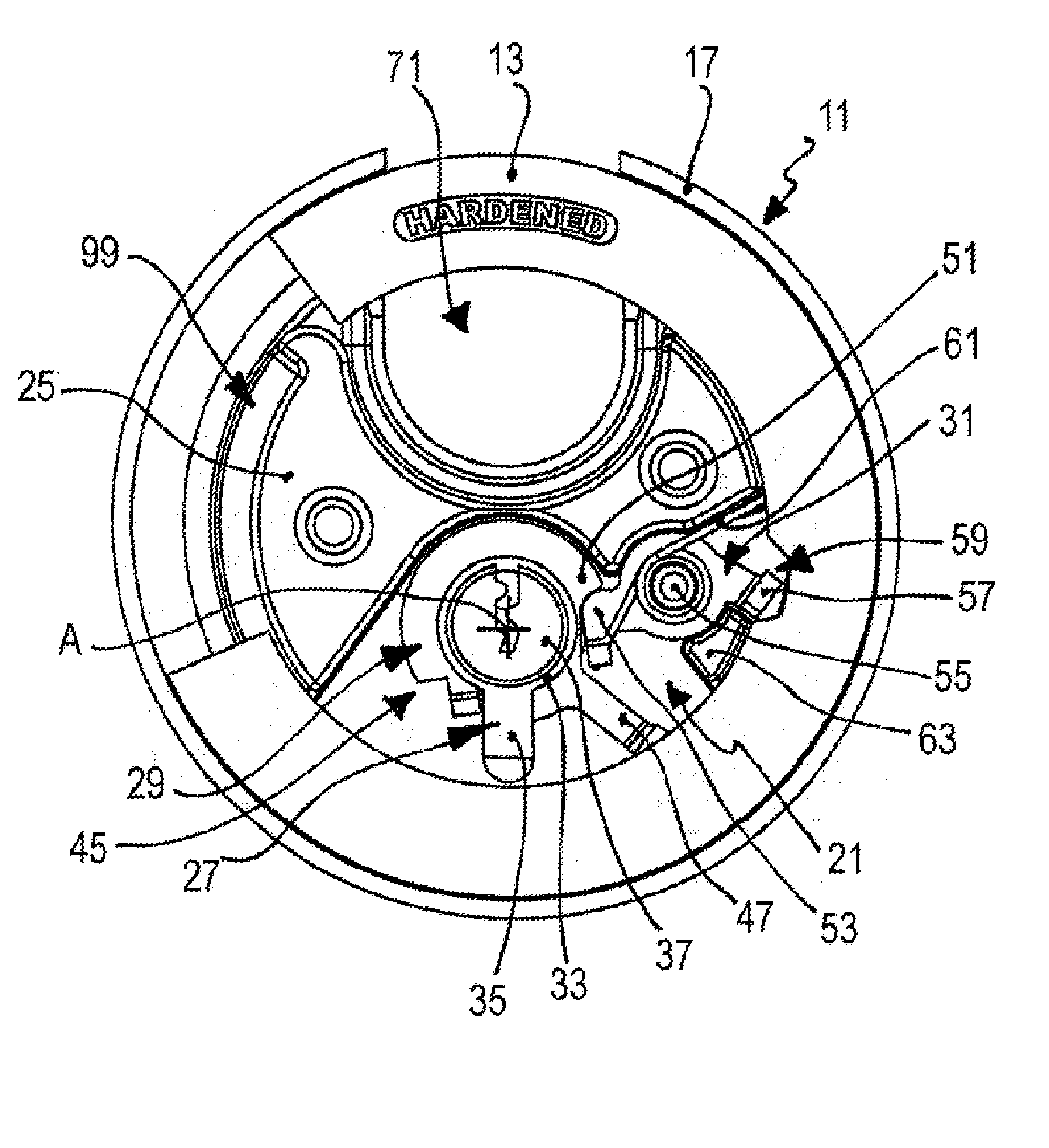
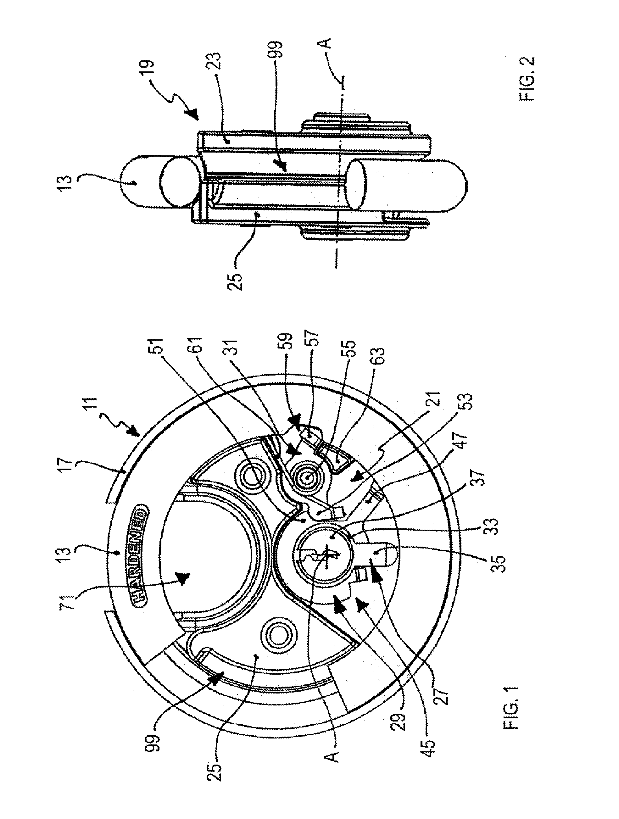
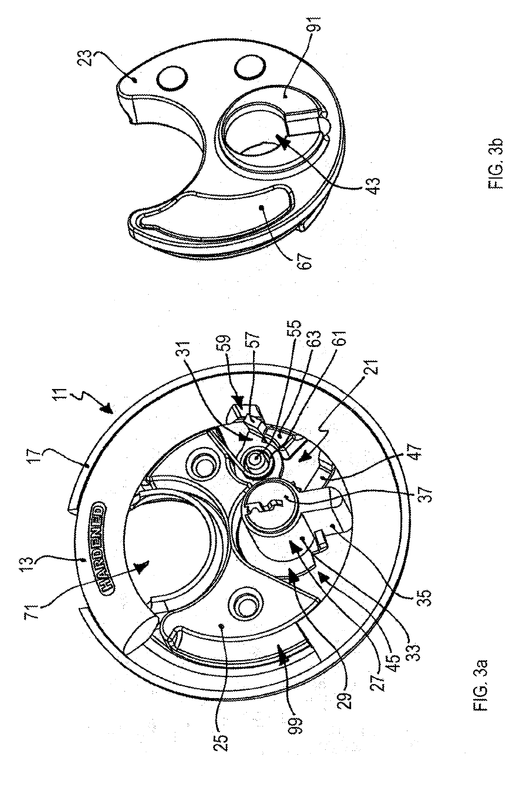
[0030]The padlock shown in the Figures has a lock body 11 and a hoop 13 which has the shape of an open ring. The hoop 13 is rotatably supported at the lock body 11, and indeed with respect to an axis of rotation A (FIGS. 1 and 2) which simultaneously forms the axis of actuation of a latching mechanism explained in the following. The hoop 13 can thus be rotated between an open position and a closed position (FIGS. 1, 2, 3a, 4a and 4b).

[0031]The lock body 11 has an outer housing which is formed by a front shell 15 (FIG. 7b) and a rear shell 17 (FIG. 7a) which are welded to one another along their respective outer peripheries in the finally installed state of the padlock.

[0032]The hoop 13, an inner housing 19 and a latching mechanism 21 are received in this outer housing.

[0033]The inner housing 19 includes a front insertion part 23 (FIGS. 3b, 5a, 5b and 5c) and a rear insertion part 25 (FIGS. 4a, 6a, 6b and 6c). The latching mechanism 21 is received in the inner housing 19 and it inclu...


PUM

PropertyMeasurementUnit
Shapeaaaaaaaaaa

Abstract

A padlock is provided that may include a lock body and a hoop which is movable between an open position and a closed position with respect to the lock body. The lock body may include an inner housing, an outer housing and a latching mechanism for latching the hoop in the closed position. The inner housing may include a first insertion part and a second insertion part which may receive the latching mechanism to form a pre-installable module. The pre-installable module may be inserted between first and second shells of the outer housing in shape matched manner to place the padlock in a fully assembled condition.

Description

CROSS-REFERENCE TO RELATED APPLICATIONS[0001]This application is a continuation of U.S. patent application Ser. No. 12 / 397,553 filed on Mar. 4, 2009, which claims the benefit and priority of German Patent Application No. DE 10 2008 012 994.1, filed Mar. 7, 2008. The entire disclosures of the above applications are incorporated herein by reference.BACKGROUND AND SUMMARY[0002]The present disclosure relates to a padlock having a lock body and a hoop which is movable between an open position and a closed position with respect to the lock body, with the lock body having an outer housing and a latching mechanism in the outer housing for the latching of the hoop in the closed position.[0003]The hoop is non-releasably connected to the lock body in such a padlock. In the unlatched state, the hoop can, however, be moved between the open position and the closed position. In the closed position, the hoop and the lock body together form a closed loop, for example to secure two chain links to one...

Claims


Application Information

Patent Timeline
IPC IPC(8): E05B67/02B23P11/00
CPCE05B67/02Y10T29/49826E05B67/28Y10T70/489Y10T70/457Y10T70/496Y10T70/48Y10T70/7921E05B67/04
Inventor GUENTHER, RAYMOND
Owner ABUS AUGUST BREMICKER SOEHNE AG
Why Eureka
Try Eureka