Fuel system for a multi-fuel engine

a fuel system and engine technology, applied in the direction of machines/engines, liquid fuel feeders, mechanical apparatuses, etc., can solve the problems of increasing operational costs, affecting pump durability, and reducing pump use, so as to reduce non-use, reduce pump degradation, and reduce the effect of pump degradation

Active Publication Date: 2012-07-05
FORD GLOBAL TECH LLC
View PDF19 Cites 65 Cited by
  • Summary
  • Abstract
  • Description
  • Claims
  • Application Information

AI Technical Summary

Benefits of technology

This patent describes how two different types of pumps are used to deliver fuel to an engine: a low pressure pump and a high pressure pump. When there is no demand for high pressure pump operation, like when the fuel levels are too high or direct injection is not needed, both pumps work together to maintain sufficient fuel pressure to supply energy to the engine. This helps reduce wear and tear on the pumps and ensures proper functioning even under extreme operating conditions.

Problems solved by technology

The technical problem addressed in this patent text needs to be identified by a senior R&D person who has read it through.

Method used


Image

  • Fuel system for a multi-fuel engine
  • Fuel system for a multi-fuel engine
  • Fuel system for a multi-fuel engine

Examples


Embodiment Construction

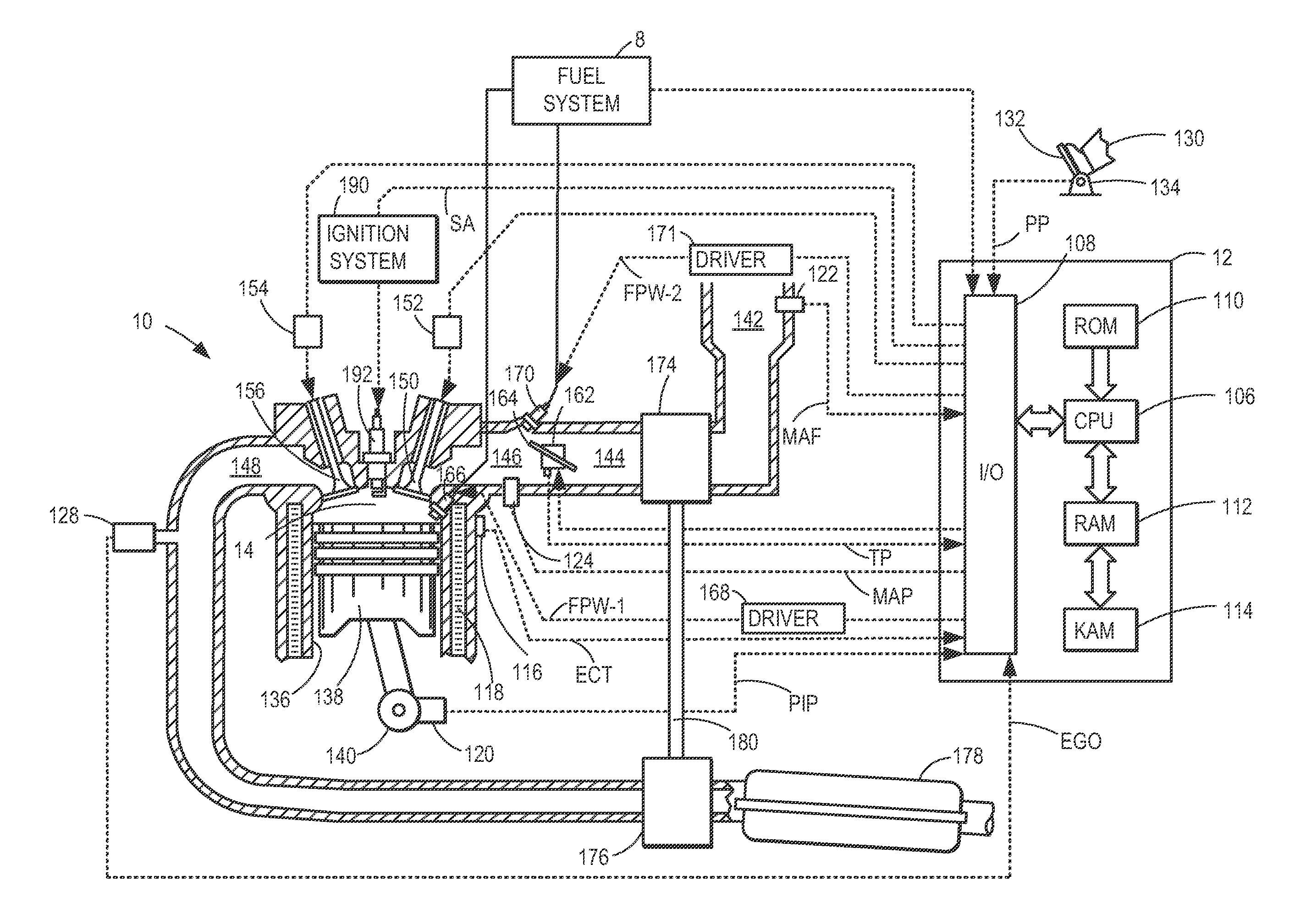
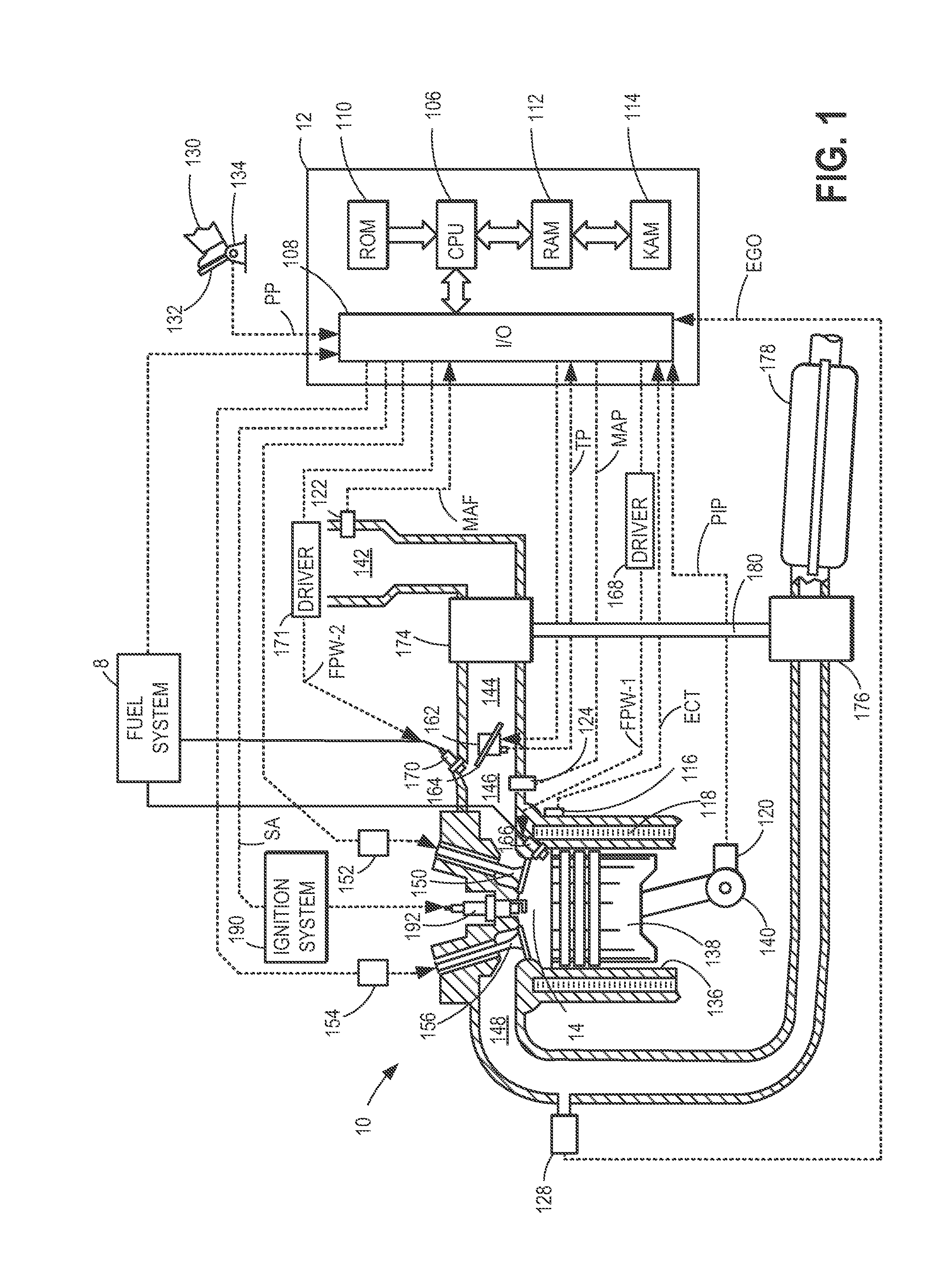
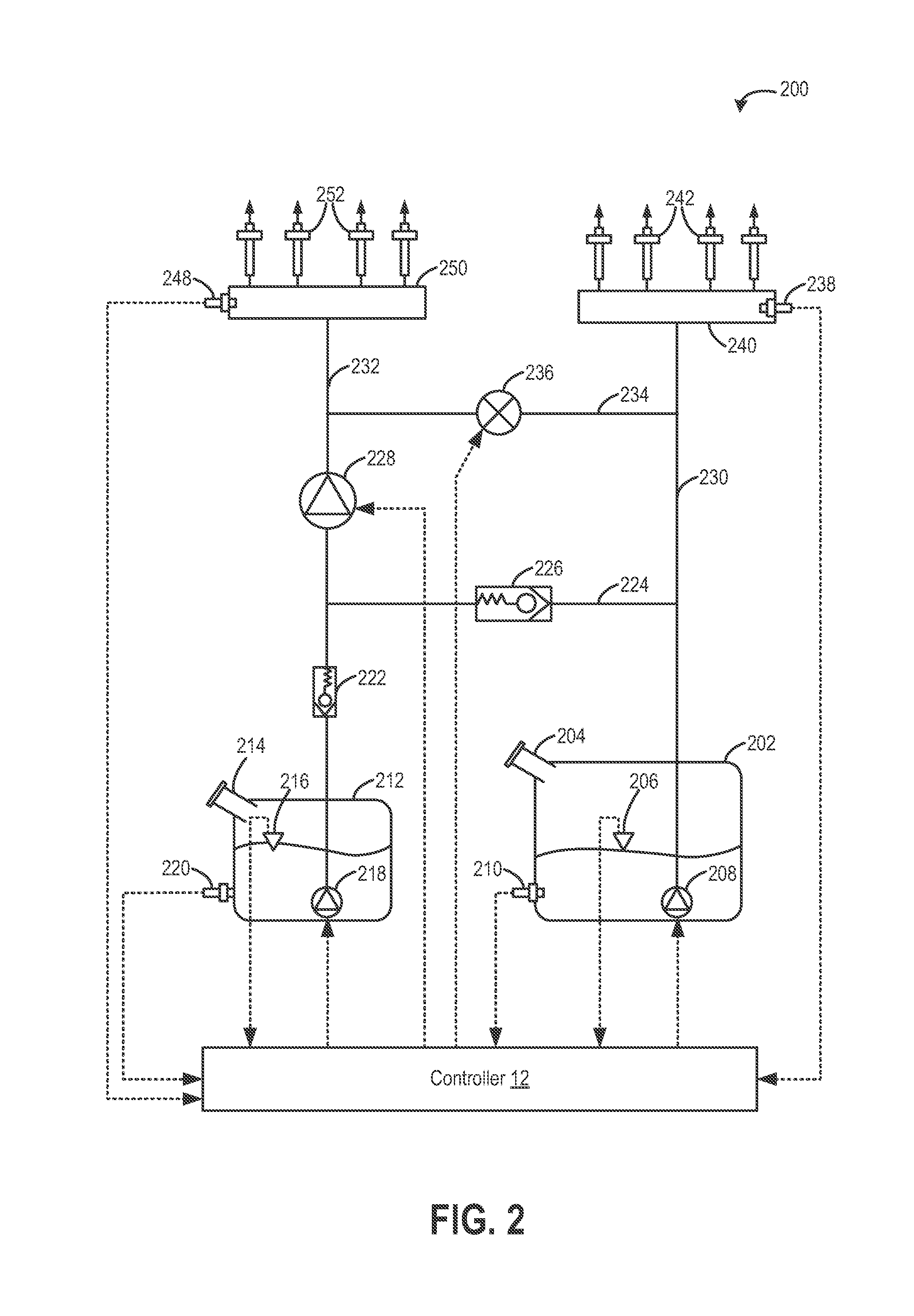
[0015]The following disclosure relates to methods and systems for operating a fuel system, such as the system of FIG. 2, configured to deliver one or more different fuel types to a combustion engine, such as the engine of FIG. 1. As shown in FIG. 2, the fuel system may include a first group of port injectors configured to port inject a selected fuel, and a second group of direct injectors configured to direct inject a selected fuel. A high pressure pump (FIG. 3) may be provided downstream of a low pressure pump for raising a pressure of the fuel to be direct injected. As such, during direct injection of fuel, the high pressure pump may be sufficiently lubricated (FIG. 8). However, during conditions when high pressure pump operation is not requested, an engine controller may maintain lubrication and / or cooling of the high pressure fuel pump by operating the low pressure pump to maintain a fuel rail pressure while adjusting a stroke amount of the high pressure pump to maintain a pump ...


PUM


Abstract

Methods and systems are provided for operating an engine fuel system including a low pressure pump and a high pressure pump. During conditions when direct injection is not requested, a fuel rail pressure is maintained by the low pressure pump and fuel is port injected. Further, a stroke amount of the high pressure pump is adjusted to maintain an outlet pressure of the high pressure pump just below the fuel rail pressure. By maintaining fuel flow within the high pressure pump when high pressure pump operation is not required, and without flowing fuel from the high pressure pump outlet into the fuel rail, the high pressure pump may be cooled and lubricated without affecting the fuel rail pressure.

Description


Claims


Application Information

Patent Timeline
Owner FORD GLOBAL TECH LLC
Why Eureka
Try Eureka