Self-propelled beach cart

Inactive Publication Date: 2012-07-05
OLIPHANT JOHN
View PDF0 Cites 5 Cited by
  • Summary
  • Abstract
  • Description
  • Claims
  • Application Information

AI Technical Summary

Benefits of technology

[0012]In a first embodiment, the invention comprises a pair of wheels coupled to the electric motors as mentioned previously and driven in a forward or reverse direction. In this first embodiment, the beach cart comprises a rigid frame formed with a cargo compartment for carrying at least beach items. In a second embodiment, the frame of the beach cart is collapsible for easy transport and storage and includes a soft-sided cargo compartment.
[0015]It is an additional object of the invention to provide an electric cart that comprises a first embodiment of the cart having a collapsible frame for transporting the cart in an automobile. The collapsible frame is easily expanded for use in transporting items to locations remote from the automobile. In a second embodiment, the electric cart is formed with a rigid frame.

Problems solved by technology

The aforementioned devices suffer from various problems in that they are not easily movable through loose sand presently found on many beaches.

Method used


Image

  • Self-propelled beach cart
  • Self-propelled beach cart
  • Self-propelled beach cart

Examples


first embodiment

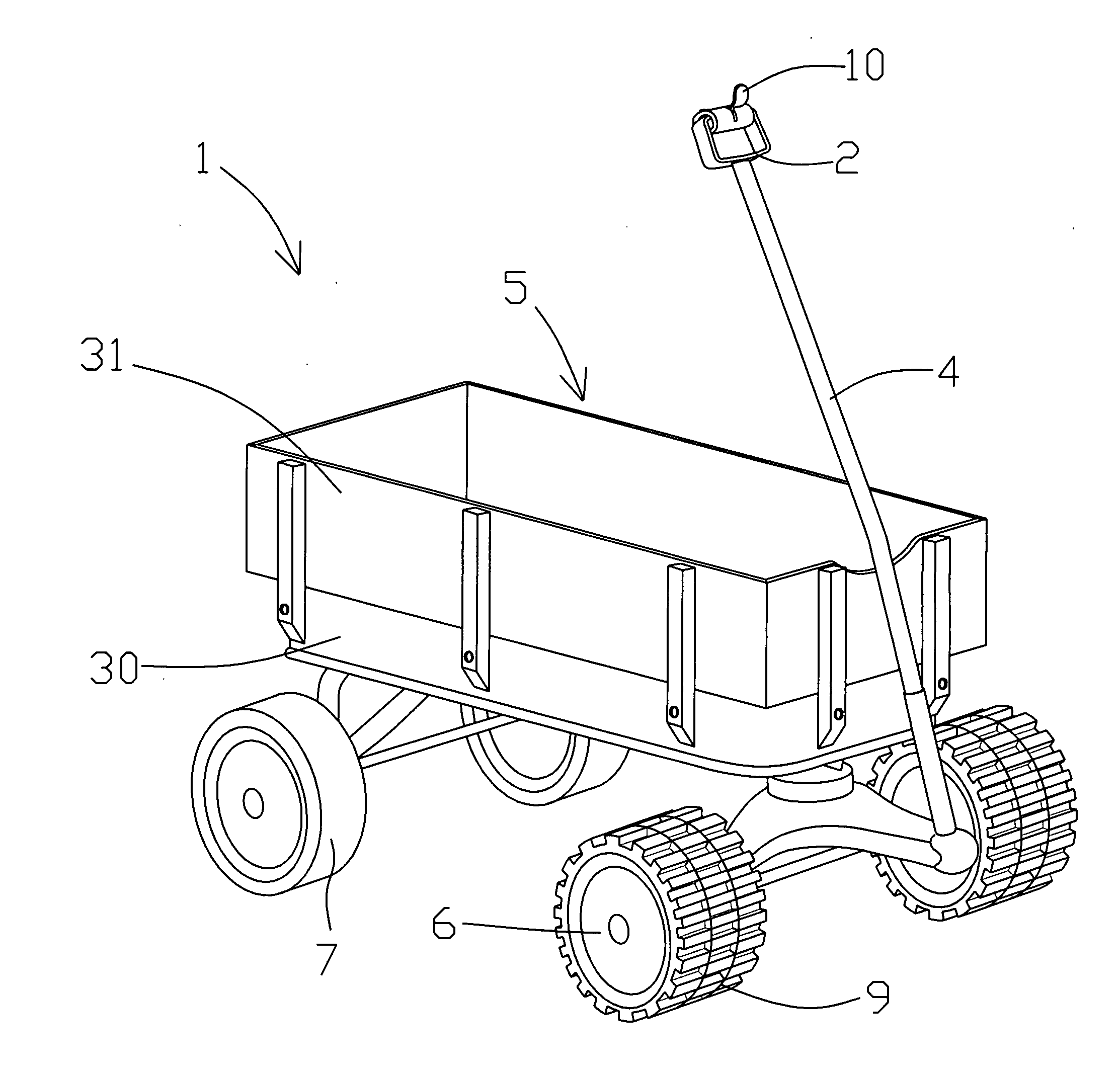
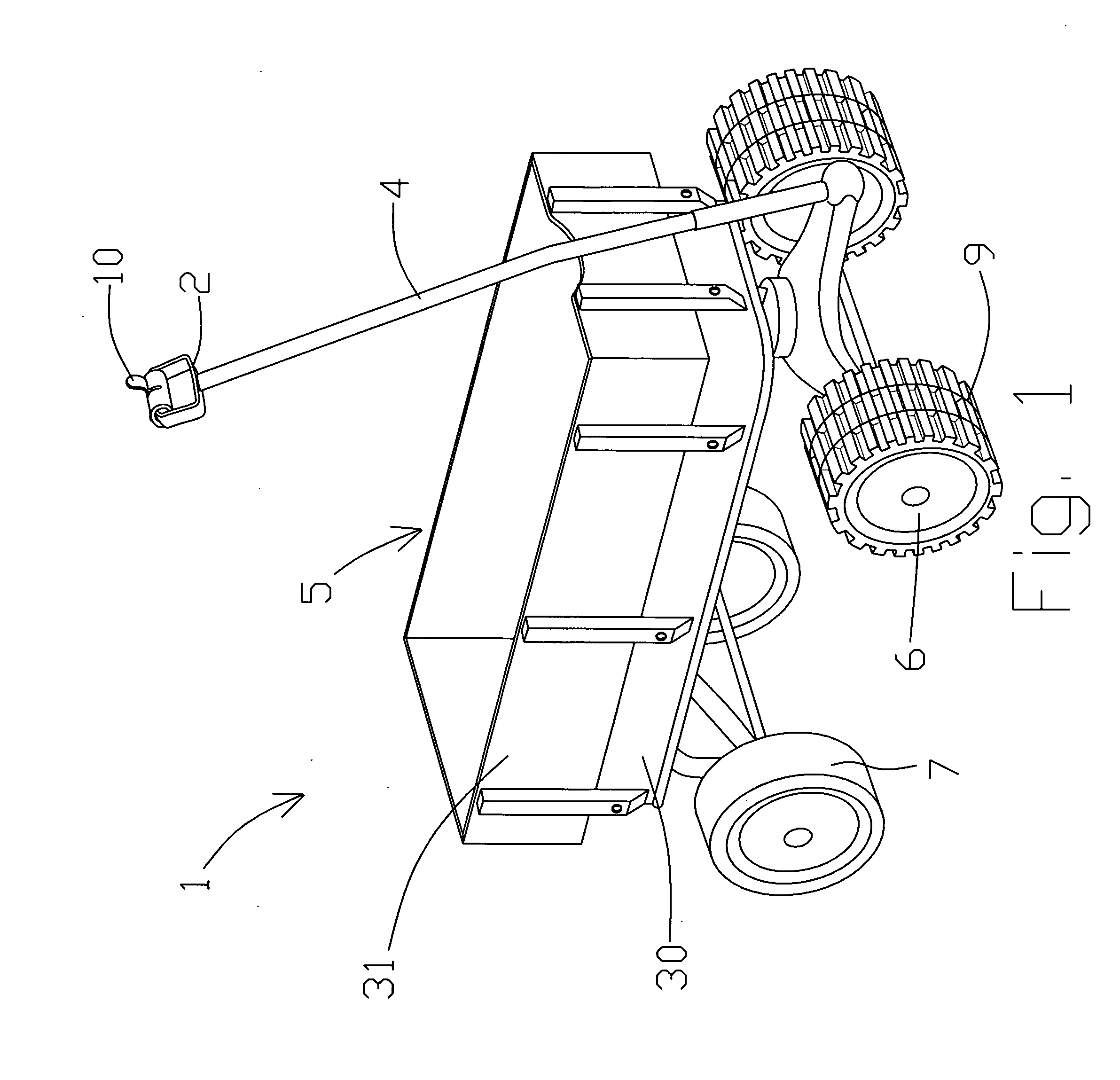
[0022]FIG. 1 depicts the invention implemented in a wagon style manner with a horizontal cargo area formed from rigid material. The cart 1 includes a frame 30 having a floor and sidewalls 31 which form a rigid cargo area or receptacle 5. When viewed from above, a footprint of the cargo area is substantially rectangular in shape. A handle 2 connects to a front end of the frame and includes a hand-hold is formed at a free end of the handle opposite the frame. A direction and accelerator switch 10 is mounted onto the hand-hold. The direction and accelerator switch includes a selector switch that toggles between forward and reverse directions as more clearly understood when viewing the electrical switch shown in FIG. 3. In a first position, electricity is flowed through a pair of DC motors 20 that powers a first axel or wheel in a forward direction. For ease in understanding the invention, the DC motors 20 are not shown in FIG. 1. In a second position, electricity is flowed through the ...

second embodiment

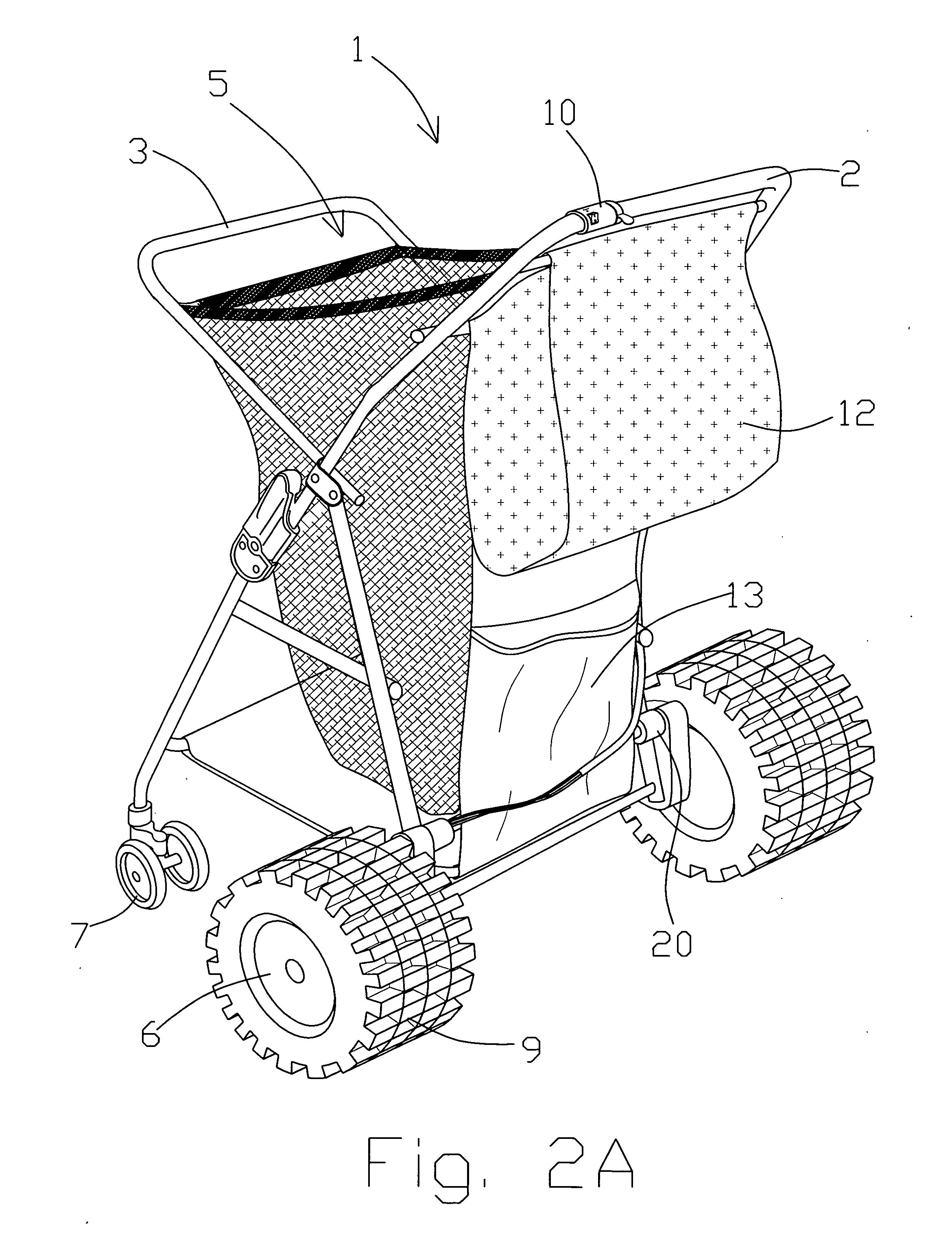
[0023]FIG. 2A shows the invention wherein the cart is implemented with a soft-sided vertical cargo area 5 formed from a collapsible material such as cloth, mesh, or netting and resembles a modern baby stroller. That is, a foot print when viewed from above is substantially square in shape. A second smaller storage area 12 for holding keys, wallets and smaller items is arranged on a side of the vertical cargo area directly under handle 2 and extends outward opposite the vertical cargo area 5. A third storage compartment 13 is formed on an outside wall of the vertical cargo area and contains a power source 30 such as a rechargeable battery, not shown in FIG. 2A. A deployable solar cell 25 or an array of solar cells, shown in FIG. 3, may be stored in this compartment and is connected to the rechargeable battery 30. The solar cell 25 operates as a trickle charger for constantly recharging the battery when deployed. In this manner, a user can be assured that the cart will be operational a...


PUM


Abstract

A motorized beach cart includes a storage area mounted atop a chassis having a plurality of axles. A motor having a corresponding hand actuated accelerator arranged on a handle of the beach cart drives one of the axles to propel the beach cart in a forward or backward direction according to a selector switch. A power source such as a battery is coupled to the motor through the accelerator for delivering a desired amount of energy to the motor to propel it in a desired direction and speed. The beach cart may include a solar cell for recharging the power source used to drive the motor.

Description

[0001]There are no related patent applications.[0002]The present application did not received federal research and / or development funding.TECHNICAL FIELD[0003]Generally, the present invention relates to a motorized beach cart in which beach items may be maintained and transported. More particularly, the present invention is a self-propelled, mobile beach cart apparatus that includes a pair of drive mechanisms which drive the beach cart in a forward or reverse direction. The beach cart is useful in transporting chairs, coolers and umbrellas across sand and other beach surfaces.BACKGROUND OF THE INVENTION[0004]Carts or wagons are known. For example, Maturo et al., U.S. Pat. No. 3,677,571 discloses a cart having a collapsible tubular frame which attaches to a carrying bag for storing articles therein. A roller connects to the frame with a cylindrical mesh screen attached to the end plates. The frame includes extending arms for accommodating a beach chair. In Abelbeck, et al., U.S. Pat....

Claims


Application Information

Patent Timeline
IPC IPC(8): B60L11/00H01M10/46B60K1/02
CPCH01M10/44B60K7/0007B60K2016/003B60L8/003Y02T10/7275B60L15/20B60L2200/30Y02T10/7005Y02T10/7083B60L11/1805Y02T10/72Y02T10/90B60L50/52Y02T10/64Y02T10/7072Y02T10/70Y02E60/10
Inventor OLIPHANT, JOHN
Owner OLIPHANT JOHN
Why Eureka
Try Eureka