Standby power shut-off outlet device and a control method for the same

a technology of standby power and outlet device, which is applied in the direction of emergency power supply arrangement, coupling device connection, pulse technique, etc., can solve the problems of wasting power and creating a risk of fire, affecting the and inconvenience for users, so as to efficiently interrupt the power consumed in the standby state, the effect of convenient operation of the outlet device and reducing the power consumed in the outl

Active Publication Date: 2012-07-05
KIM CHANG HO
View PDF2 Cites 8 Cited by
  • Summary
  • Abstract
  • Description
  • Claims
  • Application Information

AI Technical Summary

Benefits of technology

[0013]The outlet apparatus according to the present invention can automatically interrupt standby power consumed within not only the electronic product but also the outlet. Also, the outlet apparatus can efficiently interrupt standby power consumed in the electronic product according to a state of a power source of the electronic product connected to one or more plug inserters.
[0014]Further, the user can conveniently operate the outlet apparatus by directly or remotely using a remote switch unit installed in an outside of the outlet. Also, when power sources of all electronic products connected to the outlet apparatus are in an “off” state, the outlet apparatus is operated in a sleep mode and thus power consumed in the outlet may be minimized.

Problems solved by technology

In general, conventional consumer electronics consume a predetermined amount of standby power when they are plugged into a wall outlet or a multi-tap (or multi-outlet) although they are not being used, which wastes power and creates a risk of fire.
Products such as a VCR, a TV, a microwave, a dishwasher, and a cellular phone charger consume much more power in a standby state where they do not perform their functions while being connected to a power source than they do in a state where they perform their functions.
However, the outlet or the multi-tap is often located in an inconspicuous place such as behind furniture or under a desk.
Accordingly, the user should crawl under the desk or put his / her hand behind the furniture in order to control a power cut-off switch, which makes the user feel inconvenience.
As described above, since there is the cumbersomeness to turn “on” or “off” a power source of the outlet or the multi-tap for every use of the electronic product, most users usually do not turn “off” the switch while not using the electronic product, so that the waste of the standby power is still generated and coasts of the product with the switch will be increased due to the inclusion of the switch.
However, the method also has cumbersomeness in finding the remote control and then turning “on” the power source when the user desires to use the electronic product.
Also, in a case of an infrared remote control, the space where the infrared remote control can be used is limited.
Furthermore, there is a disadvantage of generating standby power in the outlet or the multi-tap itself and a problem of increasing costs according to the complexity of a circuit because there is required a power source for a control in order to receive a control signal of the remote control.

Method used


Image

  • Standby power shut-off outlet device and a control method for the same
  • Standby power shut-off outlet device and a control method for the same
  • Standby power shut-off outlet device and a control method for the same

Examples


first embodiment

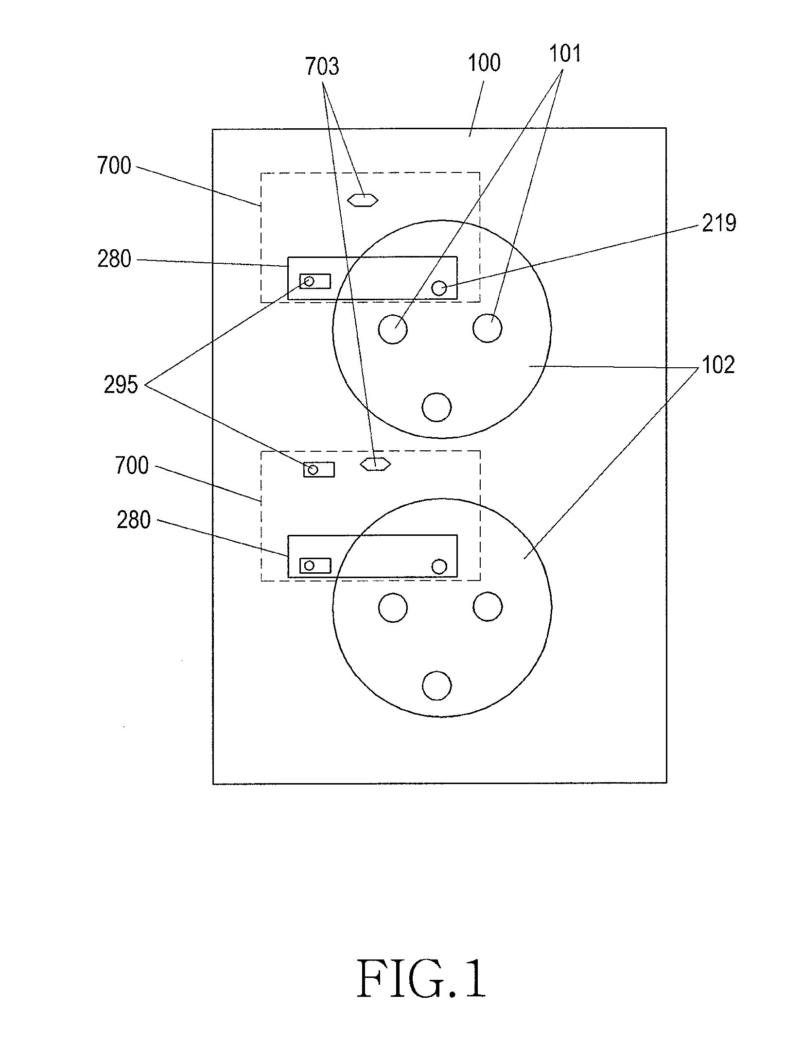
[0026]FIG. 1 is a diagram illustrating an outside of an outlet according to a first embodiment of the present invention.

[0027]Referring to FIG. 1, an outlet 100 includes one or more plug inserters 102 and one or more standby power interrupters 700. Here, the outlet 100 includes one standby power interrupter 700 corresponding to one plug inserter 102.

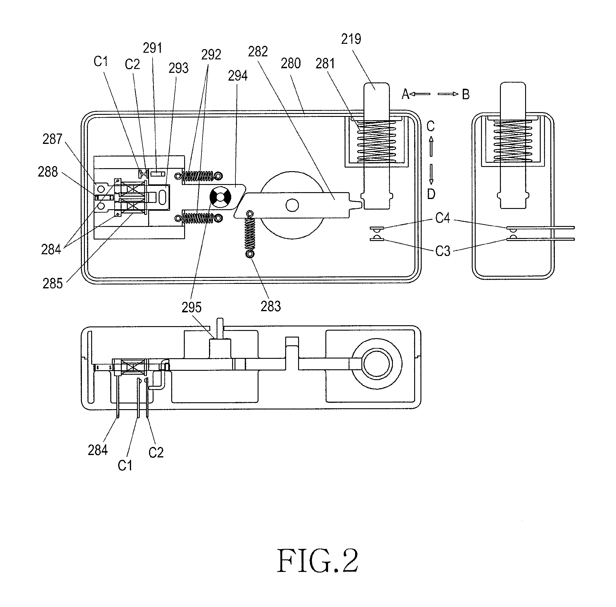
[0028]The standby power interrupter 700 includes a controller 701, an outlet power source unit 702, a jumper 703, a memory 704, an outlet switch unit 280, a current transformer 705, and a switch driver 706, and the plug inserter 102 includes a plug inserting hole 101.

[0029]The standby power interrupter 700 performs an operation of automatically interrupting standby power according to a state of an electronic product connected to the outlet 100. That is, the controller 701 of the standby power interrupter 700 measures a current flowing in an inside of the electronic product connected to the outlet 100 and determines whether a power source...

second embodiment

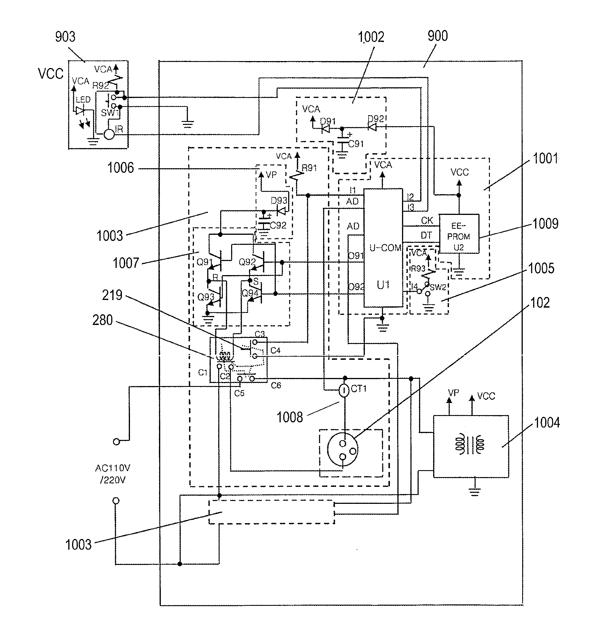
[0070]FIG. 9 is a diagram illustrating an outside of an outlet according to a second embodiment of the present invention.

[0071]Referring to FIG. 9, an outlet 900 includes one or more plug inserters 901 and one or more standby power interrupters 1003. Here, the outlet 900 includes one standby power interrupter 1003 corresponding to one plug inserter 901. Further, the outlet 900 may further include a remote switch unit 903 installed in a place allowing an easy access by a user.

[0072]FIG. 10 is a diagram illustrating an inside of an outlet according to a second embodiment of the present invention.

[0073]Referring to FIG. 10, the outlet 900 includes a controller 1001, a backup power source unit 1002, one or more standby power interrupters 1003, an outlet power source unit 1004, and a mode selector 1005, and may further include the remote switch unit 903 in an outside of the outlet 900.

[0074]The controller 1001 may include a memory 1009 in an inside or an outside of the controller 1001, a...


PUM


Abstract

An outlet or multi-outlet power strip device for interrupting standby power is provided that includes at least one standby power shut-off unit, which is provided correspondingly to at least one receptacle outlet and either supplies or shuts off power to an electronic product connected to the at least one receptacle outlet depending on the status of the electronic product; an outlet power supply, which receives power from the at least one standby power shut-off unit, and converts and supplies the input power to the outlet; a mode selector, to which a selected mode on whether the outlet should be operated in independent mode or cooperative mode is input; and a controller, which sets a standby current of the electronic product, detects the power status of the electronic product by using the set standby current, and controls the at least one standby power shut-off unit according to the detected power status.

Description

TECHNICAL FIELD[0001]The present invention relates to an outlet apparatus or a multi-tap apparatus, and more particularly to an outlet apparatus or a multi-tap apparatus having a function of interrupting standby power.BACKGROUND ART[0002]In general, conventional consumer electronics consume a predetermined amount of standby power when they are plugged into a wall outlet or a multi-tap (or multi-outlet) although they are not being used, which wastes power and creates a risk of fire. At this time, the standby power refers to power continuously consumed by consumer electronics while the consumer electronics are plugged in but switched off.[0003]The standby power is called vampire power in advanced countries as it was recognized as the main culprit of power consumption from 2 to 3 years ago. Further, the consumption of standby power becomes a subject to be actively removed as awareness of the importance of energy and the environment has been raised.[0004]Products such as a VCR, a TV, a ...

Claims


Application Information

Patent Timeline
Patent Type & Authority Applications(United States)
IPC IPC(8): H02J9/06
CPCH01R2103/00H01H3/42H01H13/18Y04S20/225H02J9/005H02J2009/007H03K2217/0036H01R13/7038H02J9/007Y02B70/30Y04S20/20A47K3/281E03C1/044E03C1/055F24H9/2007G05D23/30
Inventor KIM, CHANG-HO
Owner KIM CHANG HO
Why Eureka
Try Eureka