High power inductance device

a high-power inductance, high-efficiency technology, applied in the direction of transformer/inductance details, transformer/inductance cooling, electrical apparatus, etc., can solve the problems of increasing the temperature of various electronic devices, affecting the efficiency of the system, so as to improve the manufacturing yield, reduce the cost, and improve the effect of manufacturing eas

Active Publication Date: 2012-07-05
NJ COMPONENTS CO LTD
View PDF0 Cites 17 Cited by
  • Summary
  • Abstract
  • Description
  • Claims
  • Application Information

AI Technical Summary

Benefits of technology

[0014]In the high power inductance device according to the present invention, the ferrite magnetic core is made of the aggregate of the plurality of ferrite cores. Therefore, each of the ferrite cores may be relatively small, which improves a manufacturing yield and enables the ferrite magnetic core to be manufactured with ease and at low cost. The plurality of ferrite cores are arranged side by side such that the interval is placed between the ferrite cores and thus are not brought into direct contact with each other. Therefore, the ferrite cores are not made to collide with each other by heat deformation, vibration, or the like caused when they are operated. Consequently, problems such as core cracks and core breaking can be avoided.
[0015]Further, the plurality of ferrite cores are configured to be arranged side by side such that the magnetic paths are parallel to each other. Therefore, a required magnetic path cross-sectional area can be ensured with an increase in the number of the cores, which can flexibly deal with product specifications. Moreover, according to the present invention, a substantial heat path cross-sectional area increases with the insertion of the metal plate into each of the intervals between the ferrite cores, which can efficiently radiate generated heat from the cores to the heat radiation structure and reduce an increase in the temperature of the core. Note that because the metal plate is inserted into the interval between the ferrite cores, the existing interval can be put to effective use, which eliminates the likelihood of the device being excessively upsized.
[0016]Thus, according to the present invention, the increase in the temperature of the ferrite core can be minimized even if a heating value becomes larger, which is extremely effective in that particularly the downsizing and the cost reduction of the high power inductance device are attained.

Problems solved by technology

As is well known, the temperatures of various electronic devices increase with heat generated when the devices are operated, and components are damaged or degraded if such increases in the temperatures greatly exceed the heat resistant temperatures of materials forming the components.
However, because ferrite typically has low heat conductivity, the temperature of a part away from the cooling surface is not lowered as much as the side of the cooling surface and thus a considerable temperature difference occurs.
Particularly for the high power large inductance device, it is difficult to prevent a temperature increase in the part away from the cooling surface due to its high heating value.
Next, there is typically a problem in mass-producing large ferrite magnetic cores with excellent dimensional accuracy because ferrite is a sintered body.
The larger a ferrite magnetic core, the more the deformation of the ferrite magnetic core such as warpage is likely to occur when the ferrite magnetic core is burnt.
In an extreme case, cracks, or the like may occur in the ferrite magnetic core, which causes the degradation of a manufacturing yield.
However, when the ferrite cores are bonded together in the close contact state, they are made to collide with each other by excessive stress, vibration, or the like resulting from heat deformation caused when they are operated.
Consequently, problems such as core cracks and in an extreme case core breaking may occur, which leads to a lack in reliability.
However, such problems still remain.

Method used


Image

  • High power inductance device
  • High power inductance device
  • High power inductance device

Examples


example

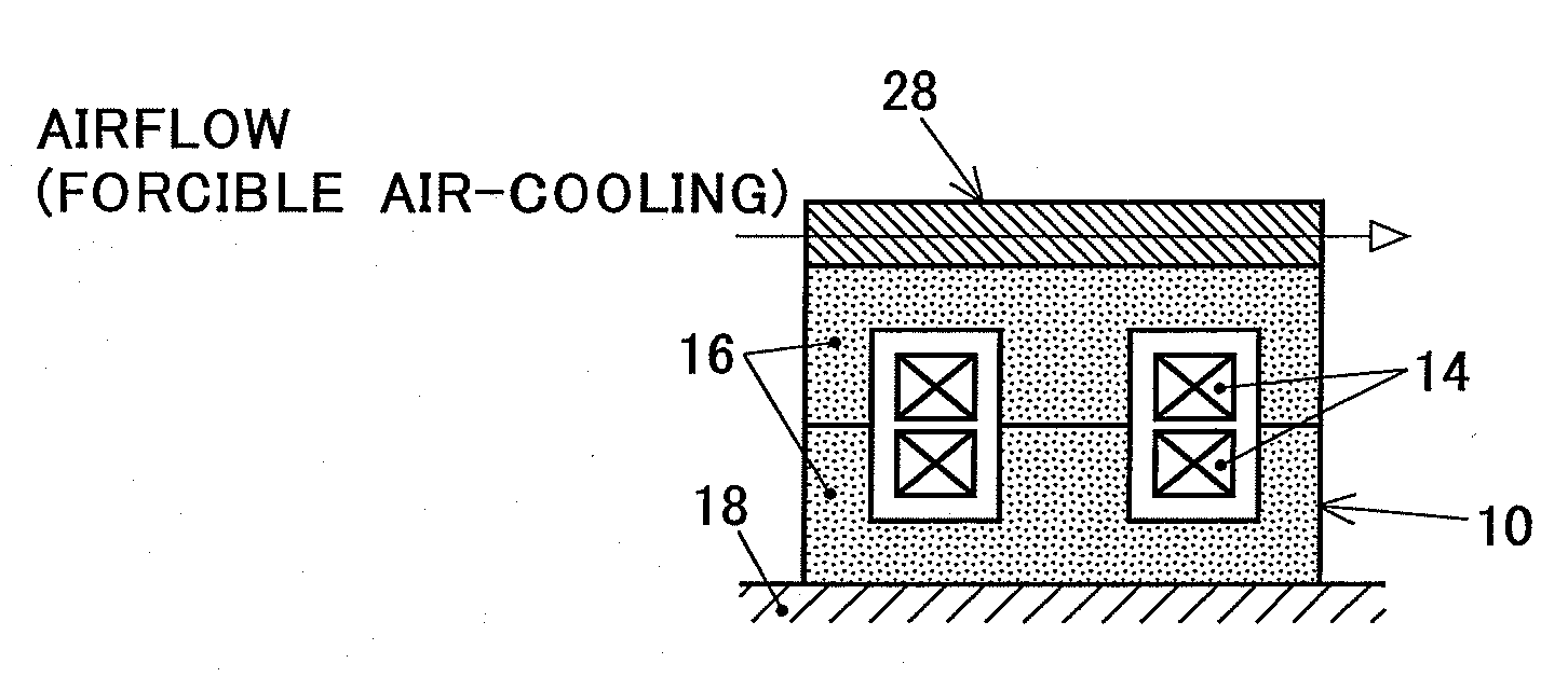
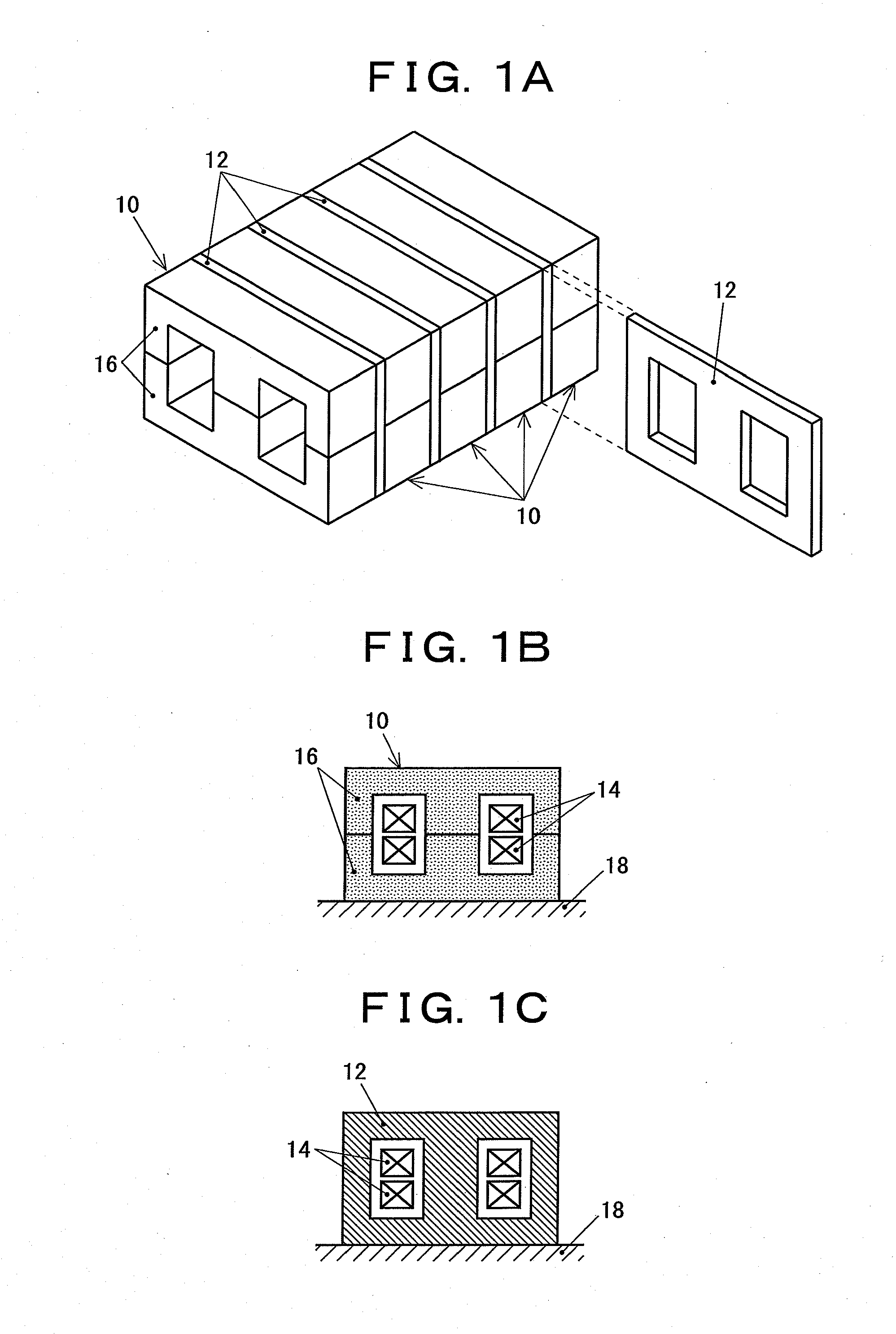
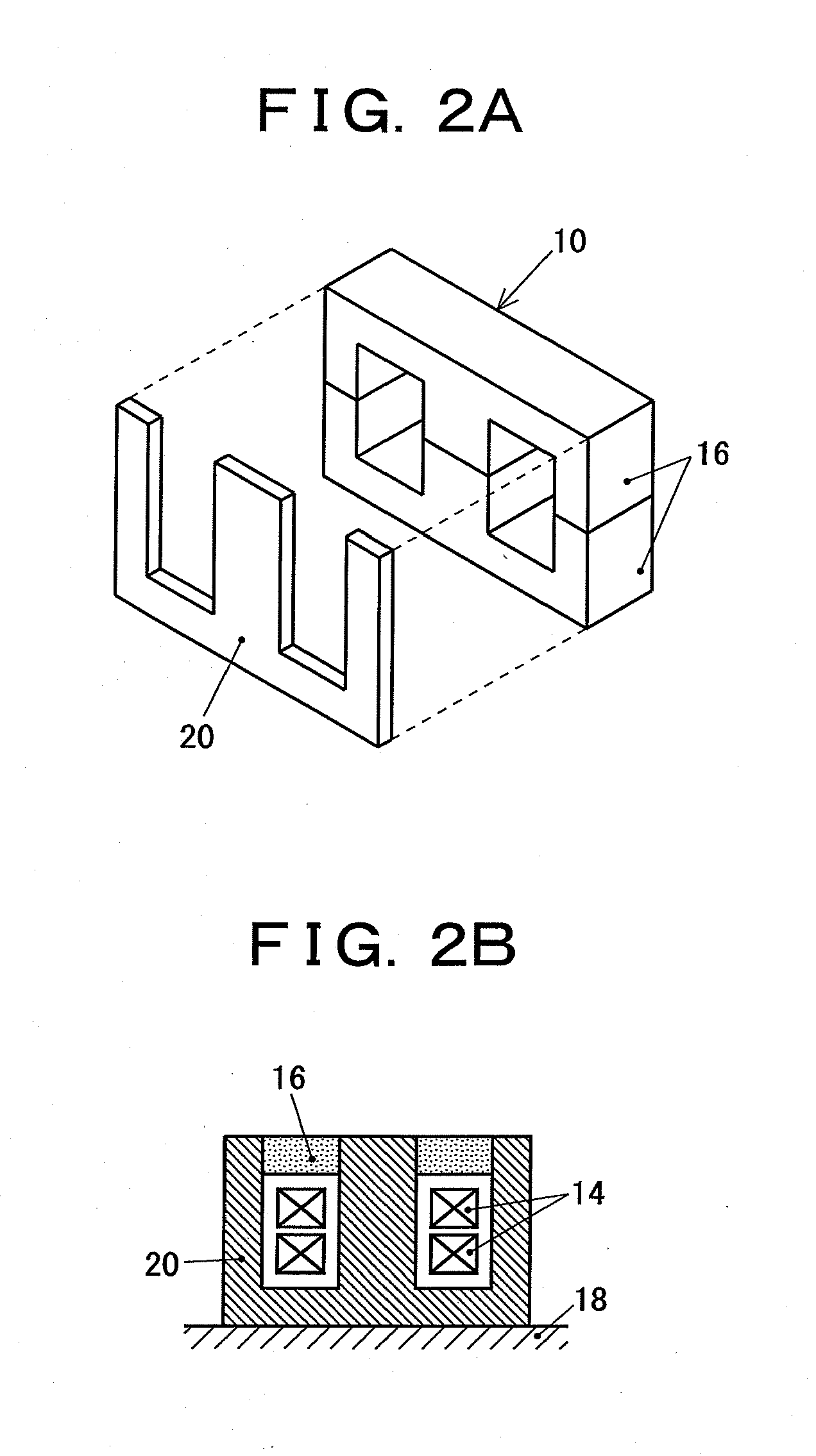
[0035]Table 1 illustrates the temperatures of the core obtained when the metal plate (aluminum plate) is inserted into each of the intervals between the adjacent ferrite cores and the winding wire is energized and driven with the configuration illustrated in FIG. 1A to FIG. 1C. Here, the core has a width of 20 mm, the metal plate has a thickness of 1 mm, and the interval between the core and the metal plate is about 0.2 mm. As evident from Table 1, the temperature of the upper surface of the core obtained when the metal plate was inserted could be made lower by about 10° C. than that of the upper surface of the core obtained when the metal plate was not inserted.

TABLE 1ComparativeExamplePresent Invention(the metal plate(the metal platewas not inserted)was inserted)Temperature of the70° C.bottom surface ofthe core T0Temperature of the95° C.85° C.upper surface ofthe core T1Temperature25° C.15° C.DifferenceΔT = T1 − T0

[0036]The partial cores constituting each of the ferrite cores may b...


PUM

PropertyMeasurementUnit
thicknessaaaaaaaaaa
thicknessaaaaaaaaaa
thicknessaaaaaaaaaa

Abstract

A high power inductance device enables a large ferrite magnetic core to be manufactured at low cost and with ease and improves heat radiation efficiency to reduce an increase in the temperature of the core. The inductance device has a ferrite magnetic core and a winding wire wound around the ferrite magnetic core and is mounted on a heat radiation structure through at least one of the front surfaces of the ferrite magnetic core. The ferrite magnetic core is made of a core aggregate obtained by arranging side by side a plurality of ferrite cores 10 having a completely-closed magnetic path structure or a quasi-closed magnetic path structure with a magnetic gap such that an interval is placed between the ferrite cores and magnetic paths are parallel to each other. The inductance device is mounted such that at least one plane surface of the peripheral surfaces of each of the ferrite cores is brought into direct or indirect contact with the heat radiation structure 18 with a metal plate 12 inserted into the interval between the ferrite cores and the common winding wire 14 wound around all the ferrite cores.

Description

TECHNICAL FIELD[0001]The present invention relates to large inductance devices through which a large current flows, and more specifically, to a high power inductance device in which a ferrite magnetic core forming magnetic paths is made of a core aggregate obtained by arranging a plurality of ferrite cores side by side such that an interval is placed between the ferrite cores and the magnetic paths are parallel to each other and in which a metal plate is inserted into each of the intervals between the ferrite cores to increase a heat path cross-sectional area and improve heat transfer efficiency to a heat radiation structure, thereby reducing a temperature increase. This technology is particularly useful for in-vehicle (car-mounted) transformers, coils, or the like having a high power capacity.BACKGROUND ART[0002]In-vehicle DC / DC converters require a transformer and a coil, which operate with a large current. Such high power inductance devices use ferrite as a magnetic core material...

Claims


Application Information

Patent Timeline
Patent Type & Authority Applications(United States)
IPC IPC(8): H01F27/22
CPCH01F27/255H01F27/22
Inventor TAKIGUCHI, TAKASHIKANAZAWA, YUKOKITAOKA, MIKIOOTA, SATOSHI
Owner NJ COMPONENTS CO LTD
Why Eureka
Try Eureka