Weather radar beam-sharpening and de-quantization

Inactive Publication Date: 2012-07-05
HONEYWELL INT INC
View PDF26 Cites 2 Cited by
  • Summary
  • Abstract
  • Description
  • Claims
  • Application Information

AI Technical Summary

Benefits of technology

[0011]The present invention makes use of a notional “desired antenna” to relax constraints (i.e., simulate a “larger antenna” with narrower beam). This enables the algorithm to converge quicker to an optimal solution, while reducing memory requirements. The present inve

Problems solved by technology

Due to the maximum physical size constraints of airborne weather radar antennas, a desired narrow antenna beam is often not achieved, thus resulting in less-than-desired detail in displayed weather data.
This is especially evident in vertical displays (relatively new to the industry) and is worse with smaller antennas (e.g., those used in business jets).
Well-known Doppler beam-sharpening techniques will not work well straight ahead of the aircraft or in the vertical direction.
Also, the natural Doppler noise of weather might be another challenge.
Small aircraft can fit only small, wide-beam antennas, thus limiting their beam-shar

Method used


Image

  • Weather radar beam-sharpening and de-quantization
  • Weather radar beam-sharpening and de-quantization
  • Weather radar beam-sharpening and de-quantization

Examples


Example

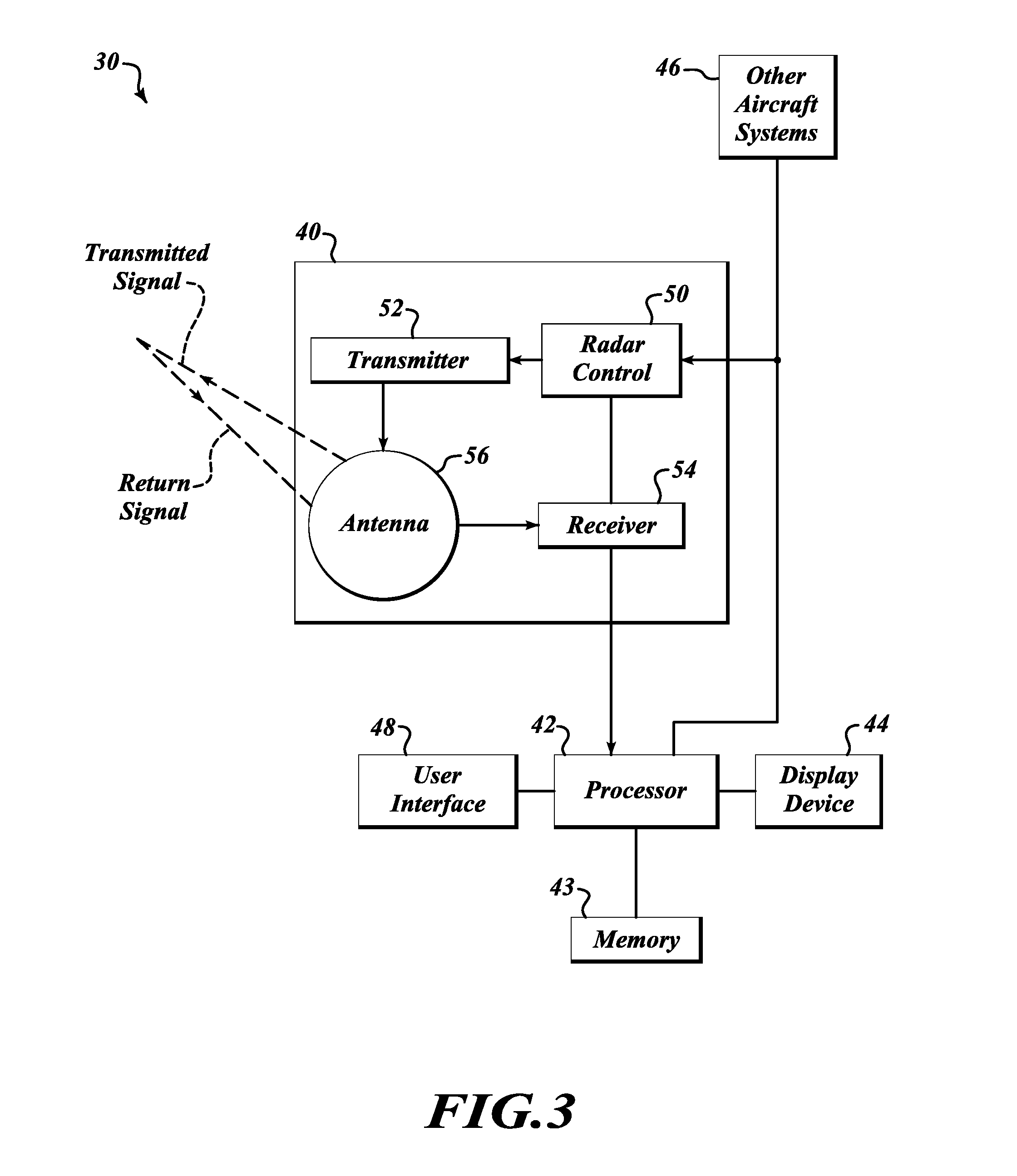
[0020]The present invention is a system, method, and computer program product for improving detail of a weather radar display at range. FIG. 1 illustrates an exemplary system 30 formed in accordance with the present invention. The system 30 includes a weather radar system 40, a processor 42, memory 43, a display device 44, other aircraft systems 46, and a user interface 48. The processor 42 is electrically coupled to the weather radar system 40, the display device 44, the other systems 46, the user interface 48, and the memory 43. An exemplary weather radar system 40 includes a radar controller 50, a transmitter 52, a receiver 54, and an antenna 56. The radar controller 50 controls the transmitter 52 and the receiver 54 for performing the sending and receiving of signals through the antenna 56 based on aircraft data (i.e., position, heading, roll, yaw, pitch, etc.) received from one or more of the other aircraft systems 46.

[0021]The weather radar system 40 receives signals that aris...


PUM


Abstract

Systems and methods for improving display quality for at range weather data of smaller antenna size radar weather systems. A processor receives a column of quantized reflectivity data associated with an antenna from a radar system. The processor adjusts the column of quantized reflectivity data based on estimated quantized reflectivity data associated with a beam pattern for an antenna that is larger than the antenna associated with the received column of quantized reflectivity data.

Description

PRIORITY CLAIM[0001]This application claims the benefit of U.S. Provisional Application Ser. No. 61 / 430,009 filed Jan. 5, 2011, the contents of which are hereby incorporated by reference.BACKGROUND OF THE INVENTION[0002]Due to the maximum physical size constraints of airborne weather radar antennas, a desired narrow antenna beam is often not achieved, thus resulting in less-than-desired detail in displayed weather data. This is especially evident in vertical displays (relatively new to the industry) and is worse with smaller antennas (e.g., those used in business jets).[0003]Well-known Doppler beam-sharpening techniques will not work well straight ahead of the aircraft or in the vertical direction. Also, the natural Doppler noise of weather might be another challenge.[0004]Small aircraft can fit only small, wide-beam antennas, thus limiting their beam-sharpening abilities.[0005]FIGS. 1 and 2 show some problems evident on a vertical display because of 15:1 expansion of vertical scale...

Claims


Application Information

Patent Timeline
IPC IPC(8): G01S13/95
CPCG01S13/953Y02A90/10
Inventor BUNCH, BRIAN P.
Owner HONEYWELL INT INC
Why Eureka
Try Eureka