Synchronization of medical imaging systems

Active Publication Date: 2012-07-05
GENERAL ELECTRIC CO
View PDF18 Cites 1 Cited by
  • Summary
  • Abstract
  • Description
  • Claims
  • Application Information

AI Technical Summary

Benefits of technology

[0008]Embodiments of the present invention allow for the synchronizing of medical data delivered by separate imaging systems

Problems solved by technology

The problem then arises of synchronizing the two types of data items: those delivered by the medical imaging system and those delivered by the intravascular sensor.

Method used


Image

  • Synchronization of medical imaging systems
  • Synchronization of medical imaging systems
  • Synchronization of medical imaging systems

Examples


Embodiment Construction

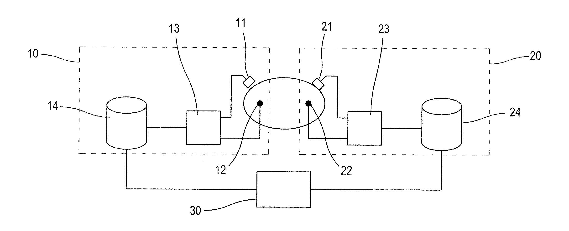
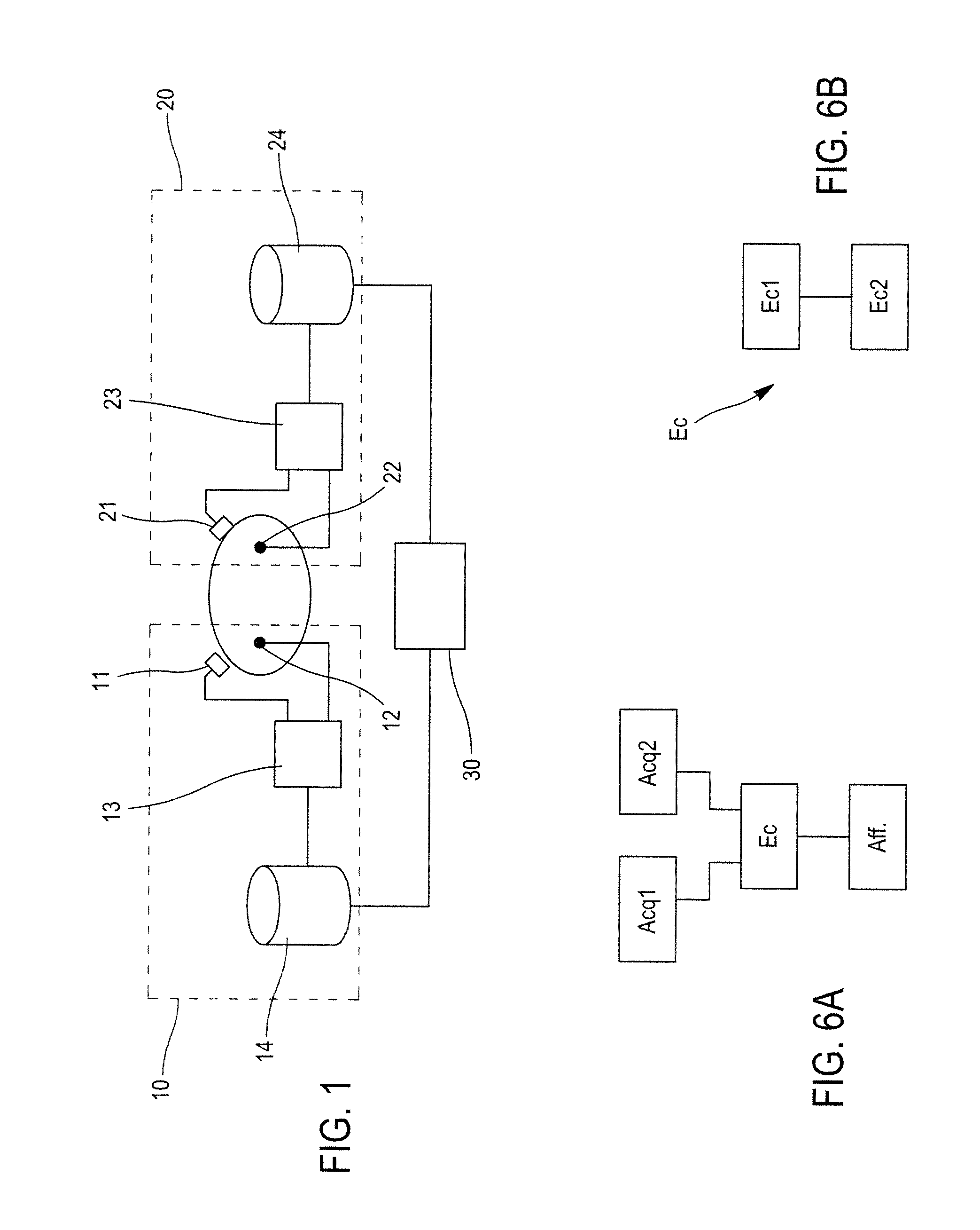
[0018]FIG. 1 illustrates two separate medical systems 10, 20. In one embodiment, the first and second systems 10, 20 are medical imaging systems. In this case, the first medical imaging system 10, for example, allows for the acquisition of radiological images of a region of interest in a patient (not illustrated) in which a contrast product has been injected.

[0019]In one embodiment, said imaging system 10 comprises an X-ray source and a detector arranged facing the source, the source and detector being connected via a C-arm. The detector may be a semiconductor image sensor, for example, comprising caesium iodide phosphorus on a transistor / photodiode array in amorphous silicon. Other suitable detectors are: CCD sensor, direct digital detector converting X-rays directly into digital signals.

[0020]The second medical imaging 20 comprises an intravascular probe 21, for example, intended to be inserted into an artery of the region of interest. This probe comprises a sensor used to acquire...


PUM


Abstract

A method for interventional imaging of synchronizing a first dataset with a second dataset is provided. The datasets represent a region of interest in a patient, wherein the first dataset and the second dataset each corresponding to two different types of information on the region of interest and wherein the datasets are acquired by separate medical systems. The method comprises aligning the first dataset and the second dataset with at least two signals representing a physiological activity of the patient, the at least two signals having been recorded by the medical systems on a common time scale with the time scale used for acquiring the datasets.

Description

BACKGROUND OF THE INVENTION[0001]1. Field of the Invention[0002]The present disclosure relates to the field of medical imaging. It more particularly concerns the processing of data, notably, images used by a practitioner during procedure on a patient.[0003]2. Description of the Prior Art[0004]For the diagnosis and treatment of coronary diseases, the form of the vessels is analyzed. For this purpose, a practitioner guides and deploys a surgical instrument inside the vascular system of a patient while being assisted by a medical imaging system. Said medical imaging system allows the acquisition, processing and real-time visualization of two-dimensional images (2D) representing the patient's vascular system and the surgical instrument. With these images, the practitioner is able to guide the instrument inside the vascular system.[0005]For diagnosis, defects such as stenosis (abnormal narrowing of a blood vessel) must be detected. To do so, the practitioner may either be provided with a...

Claims


Application Information

Patent Timeline
Patent Type & Authority Applications(United States)
IPC IPC(8): G06K9/00A61B5/352
CPCA61B5/0456A61B6/463A61B6/00A61B5/352
Inventor VAILLANT, REGIS
Owner GENERAL ELECTRIC CO
Why Eureka
Try Eureka