
Burner assembly for a lamp

Inactive Publication Date: 2012-07-05
CHEN SHYH MING +1
View PDF6 Cites 2 Cited by
  • Summary
  • Abstract
  • Description
  • Claims
  • Application Information

AI Technical Summary

Benefits of technology

[0008]Accordingly, the primary object of the present invention is to provide a lamp burner made of insulated material. The shaping of the burner is fast and the precision of the engagement is good. An oxidation problem can be avoided so as to improve the whole manufacture and yield.

Problems solved by technology

A bright lamp will generate more heat which could cause damages to the electronic parts of the lamp.
However, for the concern of the power connection to a lamp and an outer thread for connection, the complexity of manufacture is different by different material and assembly.
Additional heat dissipation module will also cause higher cost, working-hour, and defective fraction.
However, the gluing of the two parts is still time-consuming.
The connector made of metal has an oxidization problem which could cause further connection problem.
Also, cost for metal is also higher.
Therefore, a new design is imperious.
However, the groove on the integral ceramic cylinder body will weaken the intensity of the whole structure.
Damage to the assembly is easily happened under collision or temperature fluctuation.
The terminal protruding from the groove could have a contact problem due to mechanical tolerance or abrasion.

Method used


Image

  • Burner assembly for a lamp
  • Burner assembly for a lamp
  • Burner assembly for a lamp

Examples


Embodiment Construction

[0017]In order that those skilled in the art can further understand the present invention, a description will be provided in the following in details. However, these descriptions and the appended drawings are only used to cause those skilled in the art to understand the objects, features, and characteristics of the present invention, but not to be used to confine the scope and spirit of the present invention defined in the appended claims.

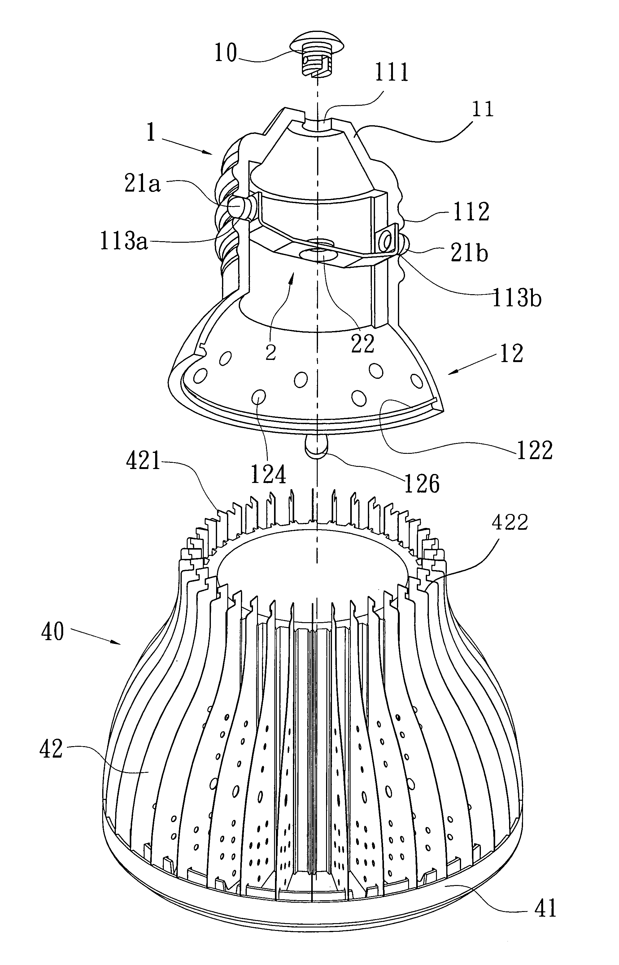
[0018]Referring to FIGS. 3 and 4, a preferable embodiment according to the present invention is illustrated. A burner assembly of the embodiment is a cylinder. The burner 1 is made of an insulated material. The insulated material can be plastic, bakelite, ceramic, or other material. The burner 1 includes a junction portion 11 and a projection portion 12. The junction portion 11 has an open hole 111 on a top thereof (shown in FIG. 5). A first electrode 10 is screwed into the open hole 111. The first electrode 10 is a bolt screwed into the open hole ...


PUM


Abstract

A burner assembly of a lamp includes a burner and at least one flexible conductor. The burner has a junction portion and a projection portion. The junction portion has an outer thread on a peripheral thereof and a open hole on a top thereof for arranging a first electrode. At least one through hole is formed to the junction portion. The flexible conductor has a positioning head on an end thereof. The positioning head severs to be a second electrode and is elastically protruded from the at least one through hole so as to be electrically connected to a lamp holder firmly.

Description

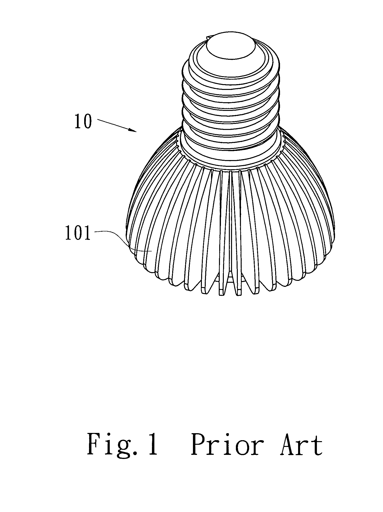
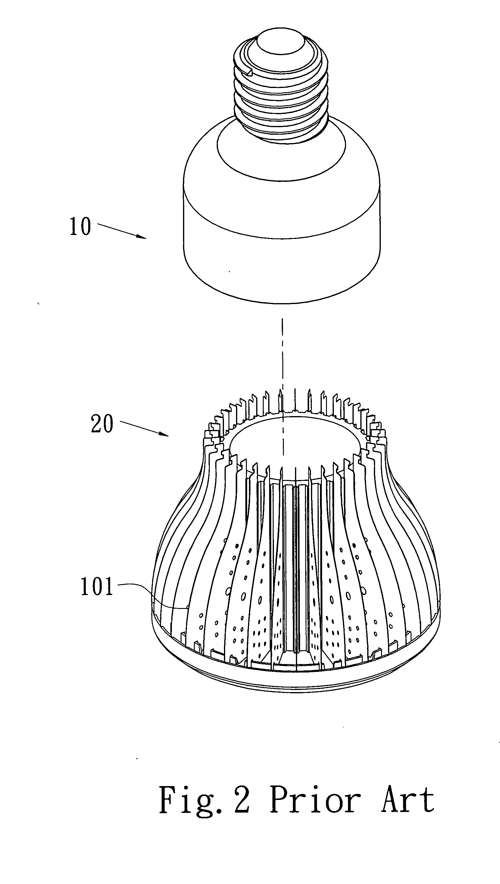
FIELD OF THE INVENTION[0001]The present invention relates to a lamp burner, and particular to a lamp burner assembly for a lamp or LED.DESCRIPTION OF THE PRIOR ART[0002]Lamps such as colorful neon lamps, lamps projecting on advertisement board, and lights or desk lights in the house are all widely used and requisite in our life.[0003]The conventional lamp bulb and the fast-developing light emitting diode (LED) are most common illumination devices. The design of the illumination device is different for various functions and purposes of illumination. Lamps nowadays are not only a light source any more, additional values are also well concerned in modern designs.[0004]Referring to FIG. 1, a conventional lamp assembly is illustrated. A bright lamp will generate more heat which could cause damages to the electronic parts of the lamp. Therefore, a lamp 10 has a plurality of fin 101 for heat dissipation. Heat dissipation can be hastened by the increase of surface area. However, for the con...

Claims


Application Information

Patent Timeline
IPC IPC(8): H01R33/22
CPCH01R33/94H01R33/22
Inventor CHEN, SHYH MINGYOU, XIANG LIN
Owner CHEN SHYH MING
Learn More