Method of positioning pipes end to end

a technology of positioning pipes and pipes, applied in the field of positioning pipes, can solve the problems of imperfect alignment of pipes by means of their inside surfaces, inconcentric diameters of inside and outside pipes, and inconvenient use of pipes

Active Publication Date: 2012-07-12
SERIMAX
View PDF2 Cites 31 Cited by
  • Summary
  • Abstract
  • Description
  • Claims
  • Application Information

AI Technical Summary

Benefits of technology

[0017]The invention seeks to remedy the drawbacks of the prior art and in particular to position the ends of two facing pipes in such a manner that the root faces or the edges of chamfers provided at each of the ends of the pipes present a maximum area of coincidence or minimal offset.

Problems solved by technology

Furthermore, it is known that manufacturing tolerances for pipes can lead to inside and outside diameters that are not concentric.
In reality, the insides of pipes are not perfectly round and manufactured pipes are not perfect in geometrical and / or dimensional terms, so aligning pipes by means of their inside surfaces is sometimes found to be imperfect.
As a result welds include defects, in particular for pipes having chamfered ends with root faces.
When external means are provided for clamping the pipes, such systems are complex or else, as mentioned above, they do not enable the root faces of the pipes to be put properly into contact.
For example this occurs when one or both of the pipes present an end that is oval instead of being circular; any other deformation of the pipes can give rise to problems of surfaces or shapes that do not coincide.

Method used


Image

  • Method of positioning pipes end to end
  • Method of positioning pipes end to end
  • Method of positioning pipes end to end

Examples


Embodiment Construction

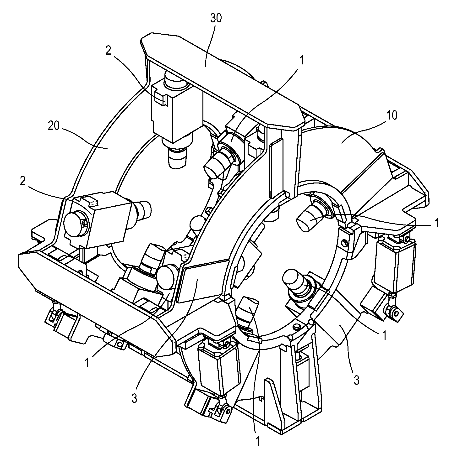
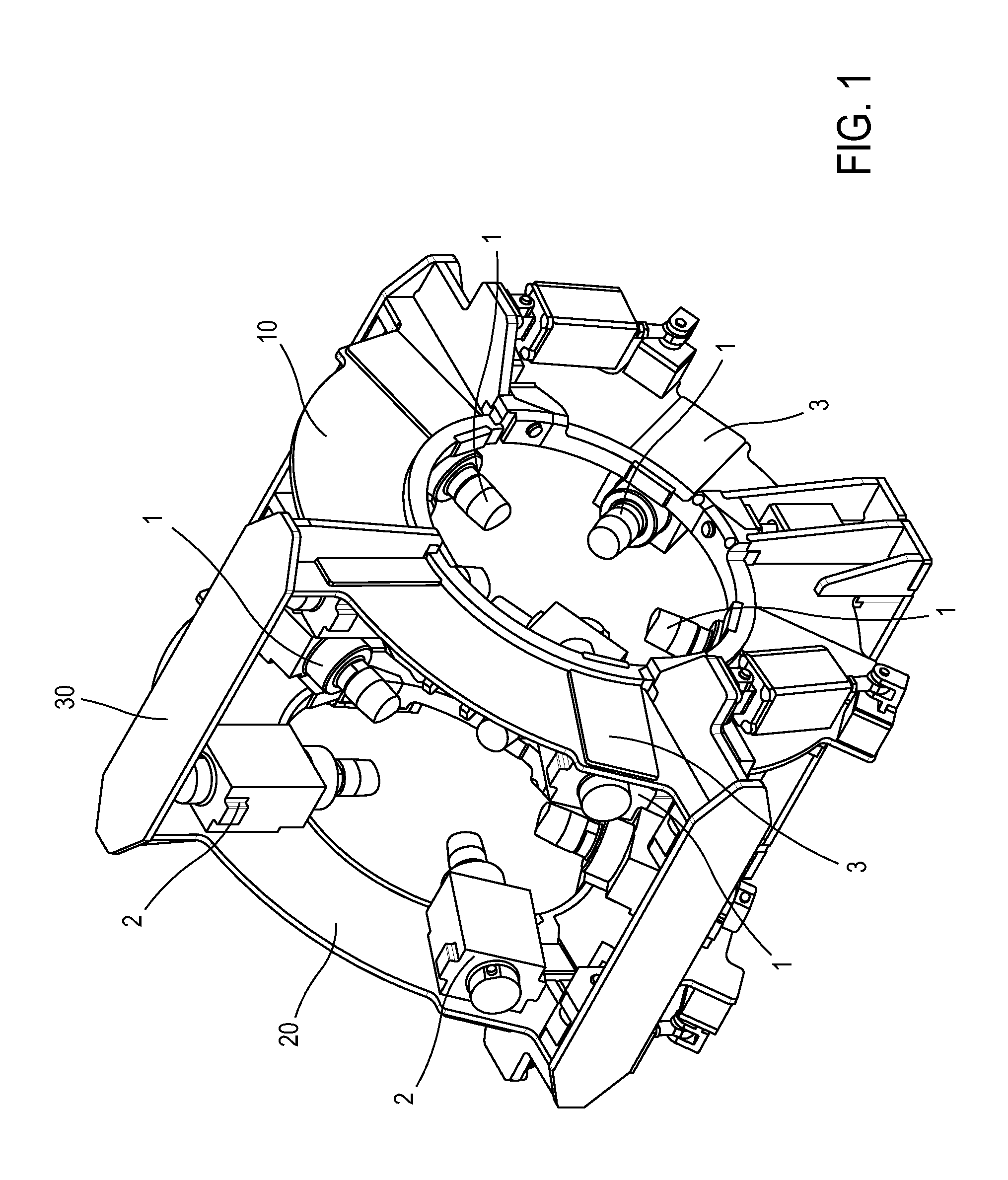
[0046]FIG. 1 is a simplified perspective view of equipment suitable for implementing the invention. Advantageously, this equipment comprises a first series of actuators 1 for positioning at one end of a first pipe that is not shown. The actuators 1 may be fastened on a first ring 10 that supports them. The actuators 1 are preferably regularly distributed angularly around said end of the first pipe.

[0047]A second series of actuators 2 for positioning at one end of the second pipe (not shown) is fastened on a second ring 20 that supports them. The actuators 2 are preferably regularly distributed angularly around said end of the second pipe.

[0048]The first and second rings 10 and 20 are spaced apart in the length direction of the pipes for positioning; connection means 30 such as yokes, bars, or the like are provided in order to leave a volume, e.g. for passing welding means or other suitable pieces of equipment. The means 30 may be of fixed length or they may be of variable length in ...


PUM

PropertyMeasurementUnit
speedaaaaaaaaaa
speedaaaaaaaaaa
pressureaaaaaaaaaa

Abstract

The present invention provides a method of positioning a first pipe facing a second pipe, the end of the first pipe being provided with a first chamfer and a first substantially annular surface placed close to its inside surface, the end of the second pipe being provided with a second chamfer and with a second substantially annular surface located close to its inside surface, said first and second annular surfaces defining a joint plane substantially perpendicular to the longitudinal axes of each of said pipes. According to the invention, a plurality of clamping actuators regularly distributed around the first and second pipes are used and controlled to shift the second pipe relative to the first pipe parallel to said joint plane as a function of a radial offset H, H′ between the first and second annular surfaces so as to guarantee a maximum facing area, referred to as a “coincidence” area for said annular surfaces.

Description

TECHNICAL FIELD OF THE INVENTION[0001]The invention relates to the field of positioning pipes facing each other, more precisely pipes that are placed end to end in order to weld their ends together. In general, in operations of this type, the pipes are first put into alignment and then clamped in order to hold them in an optimum position prior to weld them together.[0002]The invention may also apply to applications other than assembly by welding, whenever there is a need to align pipes accurately and reliably, in particular pipes of large dimensions and / or of great weight.[0003]For many years, diverse and various methods and devices have been used for these purposes.STATE OF THE PRIOR ART[0004]Mechanical solutions are known in which a ring carrying screw actuators that are regularly distributed around its circumference is placed around the outside surface (or wall) of a pipe, e.g. a metal pipe. In known manner, the ring is made up of two half-rings connected together by a hinge-type...

Claims


Application Information

Patent Timeline
Patent Type & Authority Applications(United States)
IPC IPC(8): B23P11/00
CPCY10T29/49998Y10T29/49899Y10T29/49902B23Q16/00Y10T29/49826Y10T29/53978B23K37/0533
Inventor DAGENAIS, JEAN-FRANCOIS
Owner SERIMAX
Why Eureka
Try Eureka