

Si ALLOY NEGATIVE ELECTRODE ACTIVE MATERIAL FOR ELECTRIC DEVICE
a negative electrode and active material technology, applied in the direction of electrode manufacturing process, vapour deposition manufacturing, cell components, etc., can solve the problems of large expansion-shrinkage in charge-discharge in the negative electrode, difficult to achieve capacity and energy density, and difficult to achieve a charge-discharge capacity of 372 mah/g or more, etc., to achieve the effect of preventing amorphous crystal phase transition, reducing the capacity of the negative electrode, and reducing the amorphous
- Summary
- Abstract
- Description
- Claims
- Application Information
AI Technical Summary
Benefits of technology
Problems solved by technology
Method used
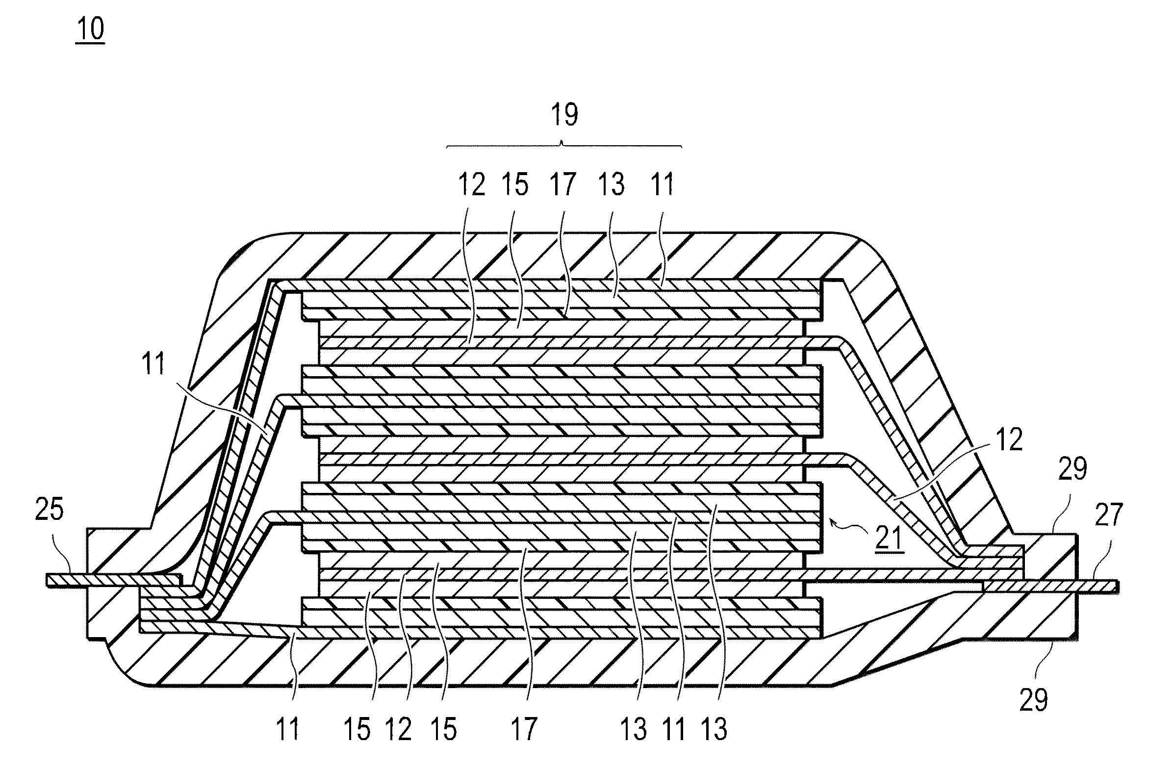
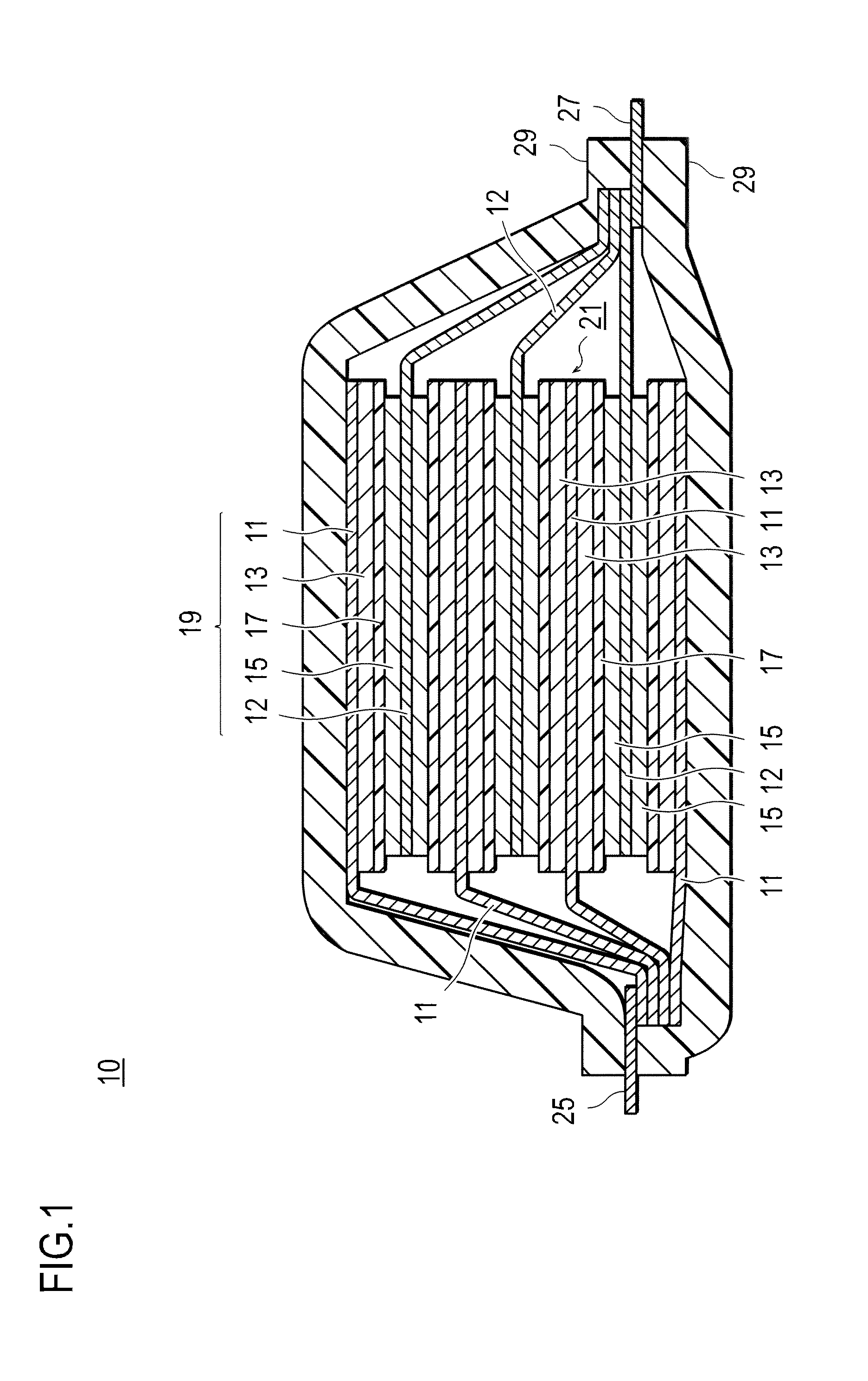
Image

Examples
example 1
Samples 1 to 48
[0131]1. Production of Cell for Evaluation
[0132](1) Production of Electrode for Evaluation
[0133]As electrodes for evaluation, thin film alloys obtained by sputtering and having various alloy compositions were used.
[0134]More specifically, as a sputtering apparatus, an independently controllable ternary DC magnetron sputtering apparatus (manufactured by Yamato-Kiki Industrial Co., Ltd.; combinatorial sputter coating apparatus; gun-sample distance: about 100 mm) was used. The thin film alloys (Samples 1 to 48) of various alloy compositions were obtained under the following sputtering conditions, target specs, and electrode sample specs.
[0135](i) More specifically, the sputtering conditions areas follows.
[0136]1) Base pressure: up to 7×10⁻⁶ Pa
[0137]2) Sputtering gas: Ar (99.9999% or more)
[0138]3) Sputtering gas introduction amount: 10 sccm
[0139]4) Sputtering pressure: 30 mTorr
[0140]5) DC power source: Si (185 W), Zn (30 to 90 W), Al (30 to 180 W)
[0141]6) Pre-sputtering t...
example 2
[0184]The initial cycle of each of the cells for evaluation (CR2032 type coin cells) using the electrodes for evaluation of Samples 14 and 42 was conducted under the same charge-discharge conditions as those of Example 1. A dQ / dV curve relative to a voltage (V) during discharge of the initial cycle is shown in FIG. 9.
[0185]As an interpretation of dQ / dV of Sample 14 based on FIG. 9, it was confirmed that crystallization of the Li—Si alloy was suppressed by adding the elements (Zn and Al) in addition to Si since the curve was gentle due to a reduction in number of downwardly projecting peaks in a region of low potential (0.4 V or less). Also, it was confirmed that decomposition of electrolyte solution was suppressed (near about 0.4 V). As used herein, Q represents a cell capacity (discharge capacity).
[0186]More specifically, the downwardly projecting sharp peak indicates a change caused by decomposition of the electrolyte solution in the vicinity of 0.4 V of Sample 42 (pure Si metal t...
example 3
[0188]A cell for evaluation (CR2032 type coin cell) using the electrode for evaluation of Sample 14 was subjected to the initial to 50th cycles under the charge-discharge conditions same as those of Example 1. The charge-discharge curves from the initial cycle to the 50th cycle are shown in FIG. 10. The charging in FIG. 10 indicates states of the charging curves in the cycles caused by the Li reaction (lithiation) in the electrode for evaluation of Sample 14. The discharging indicates states of the discharging curves of the cycles caused by Li release (delithiation).
[0189]In FIG. 10, the dense curve in each of the cycles indicates the suppressed cycle deterioration. The small kink (turn or twist) indicates that the amorphous state is maintained. Further, the small capacity difference between the charging and the discharging indicates the good charge-discharge efficiency.
[0190]From the above-described test results, it is possible to assume (estimate) the mechanism (functional mechani...
PUM
| Property | Measurement | Unit |
|---|---|---|
| energy | aaaaa | aaaaa |
| charge-discharge cycle life | aaaaa | aaaaa |
| charge-discharge capacity | aaaaa | aaaaa |
Abstract
Description
Claims
Application Information