Detection of J-Coupling Using Atomic Magnetometer

a technology of atomic magnetometer and j-coupling, which is applied in the direction of measurement using nmr, instruments, nuclear magnetic resonance analysis, etc., can solve the problems of large, expensive, immobile, and inability to remove the requirement for a superconducting magnet, and the sensitivity of low-field nmr is typically low compared to conventional high-field nmr

Active Publication Date: 2012-07-12
GOVERNMENT OF THE UNITED STATES OF AMERICA AS REPRESENTED BY THE SEC OF COMMERCE THE NAT INST OF STANDARDS & TEHCNOLOGY +1
View PDF3 Cites 28 Cited by
  • Summary
  • Abstract
  • Description
  • Claims
  • Application Information

AI Technical Summary

Benefits of technology

[0010]An embodiment of a method of detecting a J-coupling of the present invention includes providing a polarized analyte adjacent to a vapor cell of an atomic magnetometer and measuring one or more J-coupling parameters using th

Problems solved by technology

NMR experiments are conventionally performed in high magnetic fields, requiring large, immobile, and expensive superconducting magnets.
However, this practice does not remove the requirement for a superconducting magnet.
Despite the use of SQUIDs or atomic magnetometers, low-field NMR typically suffers from low sensitivity compared to con

Method used


Image

  • Detection of J-Coupling Using Atomic Magnetometer
  • Detection of J-Coupling Using Atomic Magnetometer
  • Detection of J-Coupling Using Atomic Magnetometer

Examples


example

[0081]The invention will be described in greater detail by way of a specific example. The following example is offered for illustrative purposes, and is intended neither to limit nor define the invention in any manner.

[0082]Experimental Setup

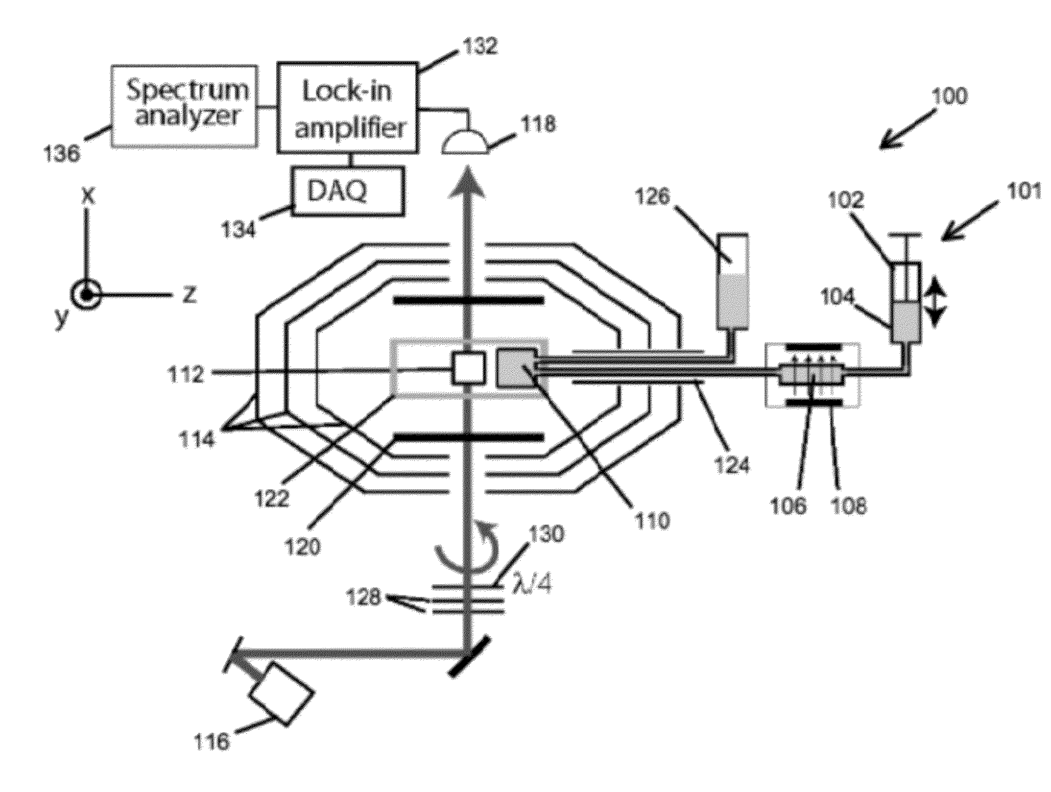
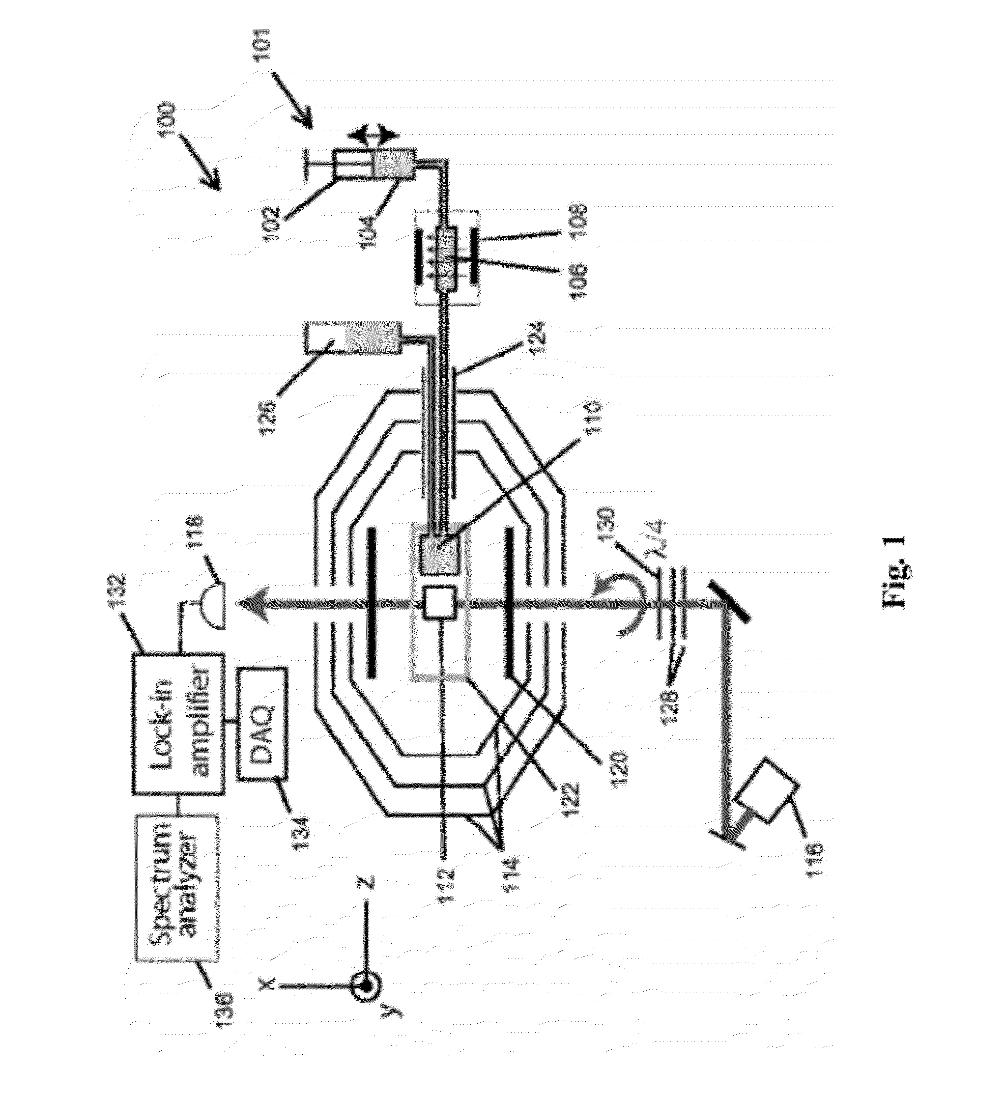
[0083]The zero-field spectrometer of the present invention is similar to that of McDermott4 and is shown schematically in FIG. 7 (a), including an atomic magnetometer, consisting of a Rb vapour cell and two lasers for optical pumping and probing, operates in the spin-exchange relaxation-free8 regime. The cell is placed inside a set of magnetic shields (not shown), and residual magnetic fields are zeroed to within ≈1 μG. The vapour cell has dimensions 5 mm□2 mm□1 mm, contains 87Rb and 1300 torr of N2 buffer gas mm, and was microfabricated using lithographic patterning and etching techniques.

[0084]The cell is heated to 210° C. via an electric heating element wound around an aluminium-nitride spool. The sensitivity of the magnetometer is about 0.15...


PUM


Abstract

An embodiment of a method of detecting a J-coupling includes providing a polarized analyte adjacent to a vapor cell of an atomic magnetometer; and measuring one or more J-coupling parameters using the atomic magnetometer. According to an embodiment, measuring the one or more J-coupling parameters includes detecting a magnetic field created by the polarized analyte as the magnetic field evolves under a J-coupling interaction.

Description

RELATED APPLICATIONS[0001]This application is the national phase application of International application number PCT / US2010 / 030897, filed Apr. 13, 2010, which claims priority to and the benefit of U.S. Provisional Application No. 61 / 168,795, filed on Apr. 13, 2009, which is hereby incorporated by reference in its entirety.STATEMENT OF GOVERNMENT SUPPORT[0002]This invention was made with government support under Contract No. DE-AC02-05CH11231 awarded by the U.S. Department of Energy and with support from the National Institute of Standards and Technology, a non-regulatory agency within the U.S. Department of Commerce. The government has certain rights in this invention.BACKGROUND OF THE INVENTION[0003]The present invention relates to the field of nuclear magnetic resonance and, more particularly, to the field of detection of J- or scalar coupling.[0004]Nuclear magnetic resonance (NMR) endures as one of the most powerful analytical tools for detecting chemical species and elucidating ...

Claims


Application Information

Patent Timeline
IPC IPC(8): G01R33/12
CPCG01N24/08G01N24/087G01R33/26G01R33/5605G01R33/46G01R33/4608G01R33/445
Inventor LEDBETTER, MICAH P.CRAWFORD, CHARLES W.WEMMER, DAVID E.PINES, ALEXANDERKNAPPE, SVENJAKITCHING, JOHNBUDKER, DMITRY
Owner GOVERNMENT OF THE UNITED STATES OF AMERICA AS REPRESENTED BY THE SEC OF COMMERCE THE NAT INST OF STANDARDS & TEHCNOLOGY
Why Eureka
Try Eureka