Audio Signal Decoder, Method for Decoding an Audio Signal and Computer Program Using Cascaded Audio Object Processing Stages

Active Publication Date: 2012-07-12
FRAUNHOFER GESELLSCHAFT ZUR FOERDERUNG DER ANGEWANDTEN FORSCHUNG EV
View PDF1 Cites 86 Cited by
  • Summary
  • Abstract
  • Description
  • Claims
  • Application Information

AI Technical Summary

Benefits of technology

[0060]In an embodiment, the object separator is configured to provide the second audio information such that the second audio information describes more than two audio objects of the second audio object type. Embodiments according to the invention allow for a flexible adjustment of the number of audio objects of the second audio object type, which is significantly facilitated by the cascaded structure of the processing.
[0061]In an embodiment, the object separator is configured to obtain, as the second audio information, a one-channel audio signal representation or a two-channel audio signal representat

Problems solved by technology

However, the reconstructed object signals 820b may deviate somewhat from the original object signals x1 to xN, for example, because the side information 814 is not quite sufficient for a perfect reconstruction due to the bitrate constraints.
In the SAOC decoder 920, the extraction of the object signals 924 is performed separately from the mixing/rendering which allows for a separation of the object decoding functionality from the mixing/rendering functionality but brings along a relatively high computational complexity.
For a mono output, the rendering matrix coefficients are given by r1 to rN.Effectively, the separation of the object signals is rarely executed (or even never executed), since both the separation step (indicated by the object separator 820a) and the mixing step (indicated by the mixer 820c) are combined into a single transcoding step, which often results in an enormous reduction in computational complexity.
It has been found that such a scheme is tremendously efficient, both in terms of transmission bitrate (it is only

Method used


Image

  • Audio Signal Decoder, Method for Decoding an Audio Signal and Computer Program Using Cascaded Audio Object Processing Stages
  • Audio Signal Decoder, Method for Decoding an Audio Signal and Computer Program Using Cascaded Audio Object Processing Stages
  • Audio Signal Decoder, Method for Decoding an Audio Signal and Computer Program Using Cascaded Audio Object Processing Stages

Examples


Embodiment Construction

1. Audio Signal Decoder According to FIG. 1

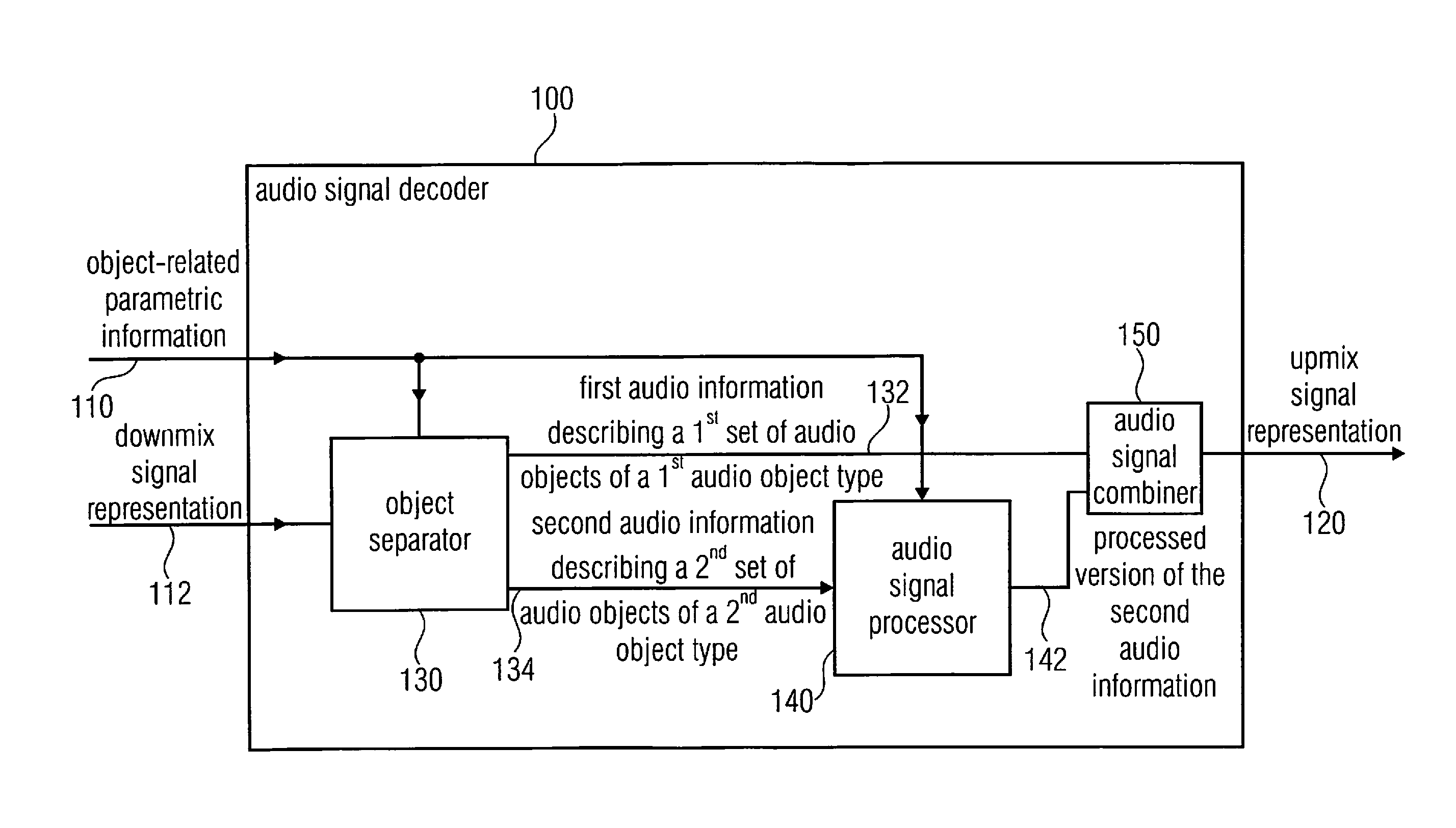
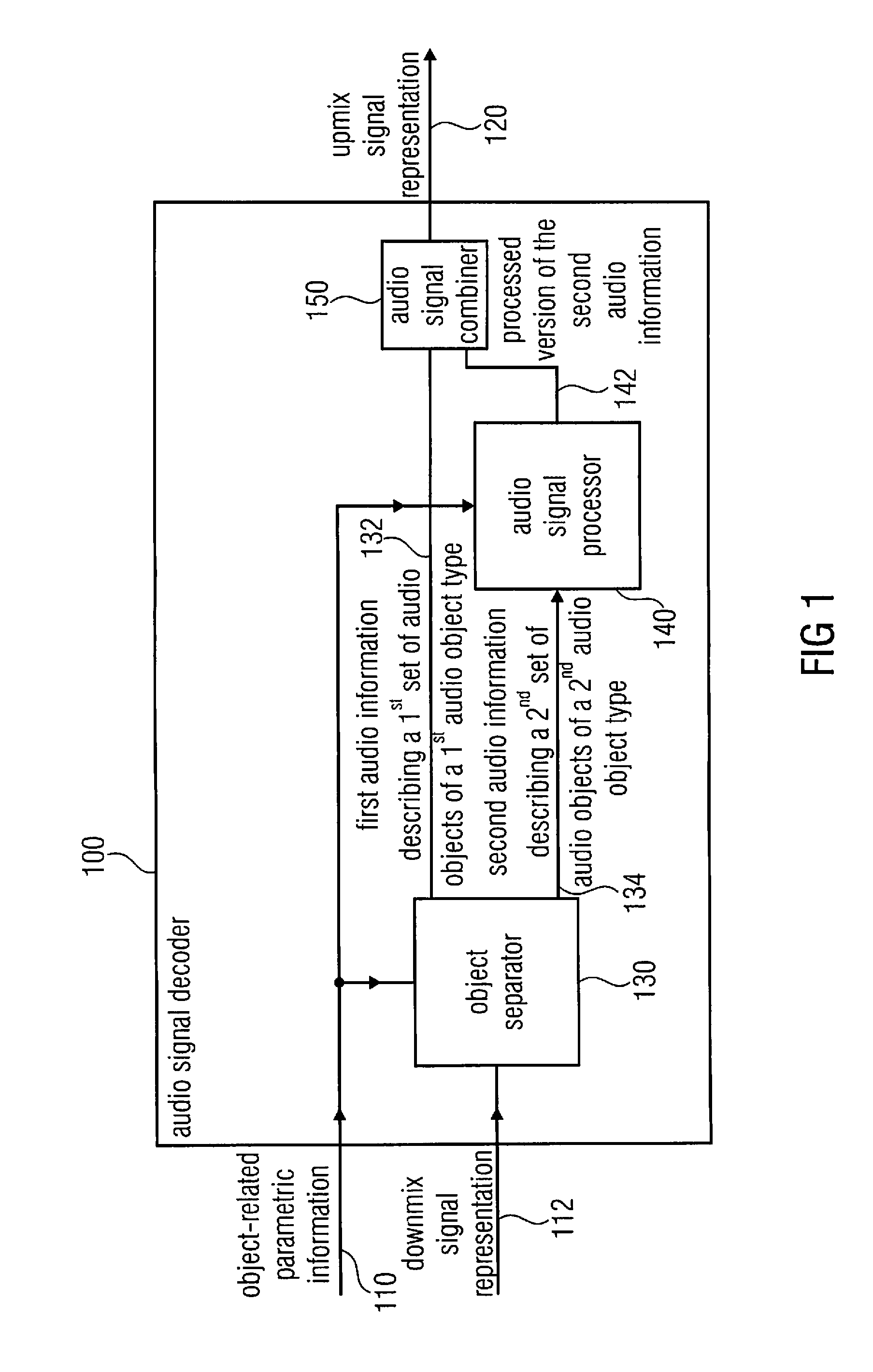
[0086]FIG. 1 shows a block schematic diagram of an audio signal decoder 100 according to an embodiment of the invention.

[0087]The audio signal decoder 100 is configured to receive an object-related parametric information 110 and a downmix signal representation 112. The audio signal decoder 100 is configured to provide an upmix signal representation 120 in dependence on the downmix signal representation and the object-related parametric information 110. The audio signal decoder 100 comprises an object separator 130, which is configured to decompose the downmix signal representation 112 to provide a first audio information 132 describing a first set of one or more audio objects of a first audio object type and a second audio information 134 describing a second set of one or more audio objects of a second audio object type in dependence on the downmix signal representation 112 and using at least a part of the object-related parametric informat...


PUM


Abstract

An audio signal decoder for providing an upmix signal representation in dependence on a downmix signal representation and an object-related parametric information includes an object separator configured to decompose the downmix signal representation, to provide a first audio information describing a first set of one or more audio objects of a first audio object type and a second audio information describing a second set of one or more audio objects of a second audio object type, in dependence on the downmix signal representation and using at least a part of the object-related parametric information.

Description

CROSS-REFERENCE TO RELATED APPLICATIONS[0001]This application is a continuation of copending International Application No. PCT / EP2010 / 058906, filed Jun. 23, 2010, which is incorporated herein by reference in its entirety, and additionally claims priority from U.S. Application No. 61 / 220,042, filed Jun. 24, 2009, which is also incorporated herein by reference in its entirety.BACKGROUND OF THE INVENTION[0002]Embodiments according to the invention are related to an audio signal decoder for providing an upmix signal representation in dependence on a downmix signal representation and an object-related parametric information.[0003]Further embodiments according to the invention are related to a method for providing an upmix signal representation in dependence on a downmix signal representation and an object-related parametric information.[0004]Further embodiments according to the invention are related to a computer program.[0005]Some embodiments according to the invention are related to an...

Claims


Application Information

Patent Timeline
IPC IPC(8): H04R5/00
CPCG10H1/361G10H2210/301G10L19/008H04S2420/07H04S7/30H04S2400/11G10L19/20H04S3/00
Inventor HELLMUTH, OLIVERFALCH, CORNELIAHERRE, JUERGENHILPERT, JOHANNESTERENTIV, LEONRIDDERBUSCH, FALKO
Owner FRAUNHOFER GESELLSCHAFT ZUR FOERDERUNG DER ANGEWANDTEN FORSCHUNG EV
Why Eureka
Try Eureka