Percutaneous heart pump

a percutaneous heart pump and ventricular assist device technology, applied in the field of percutaneous heart pumps, can solve the problems of increasing etc., and achieve the effect of reducing the risk of heart failure and reducing the risk of strok

Active Publication Date: 2012-07-12
TUBEMASTER INC +2
View PDF24 Cites 262 Cited by
  • Summary
  • Abstract
  • Description
  • Claims
  • Application Information

AI Technical Summary

Problems solved by technology

Heart disease is a major health problem that claims many lives per year.
Surgical insertion, however, can cause additional serious stresses in heart failure patients.
Conventional fixed cross-section ventricular assist devices designed to provide near full heart flow rate are too large to be advanced percutaneously, e.g., through the femoral artery.

Method used


Image

  • Percutaneous heart pump
  • Percutaneous heart pump
  • Percutaneous heart pump

Examples


Embodiment Construction

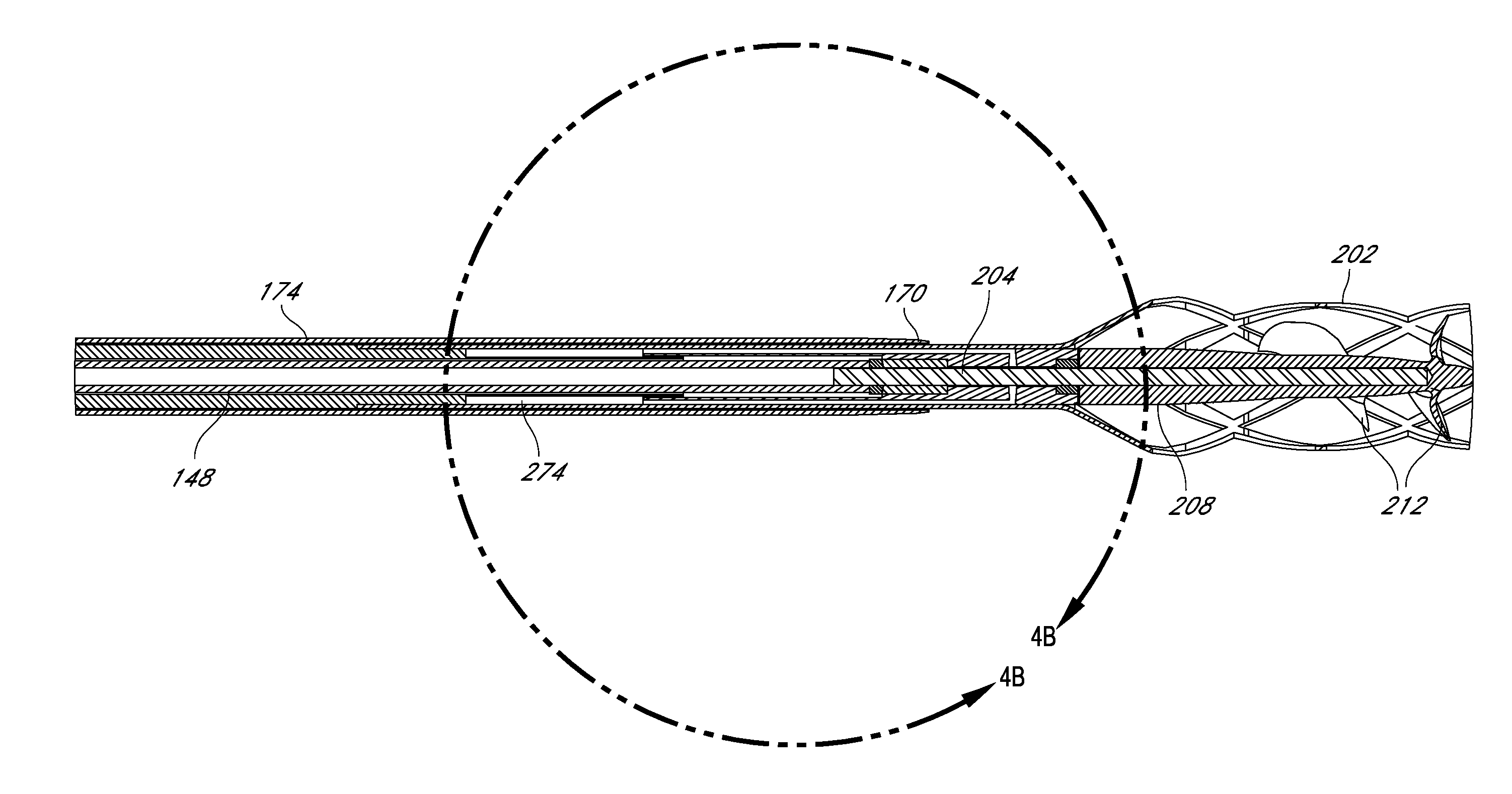
[0036]Major components of heart pumps that can be applied percutaneously to a patient are described below in Section I. Section II describes various structures that facilitate the rotatable support of a cantilevered impeller. Section III describes various structures that facilitate deployment and / or retrieval of one or more components of the distal end 108 of the heart pump 10 within the cardiovascular system. Section IV describes various methods and techniques in connection with specific structures of heart pumps

I. Overview of Heart Pumps

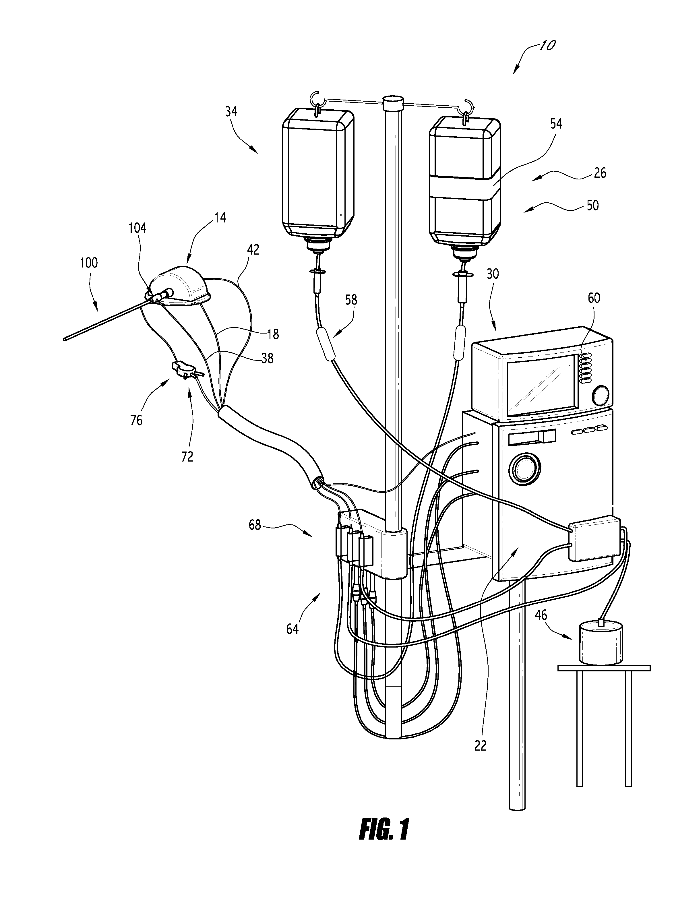
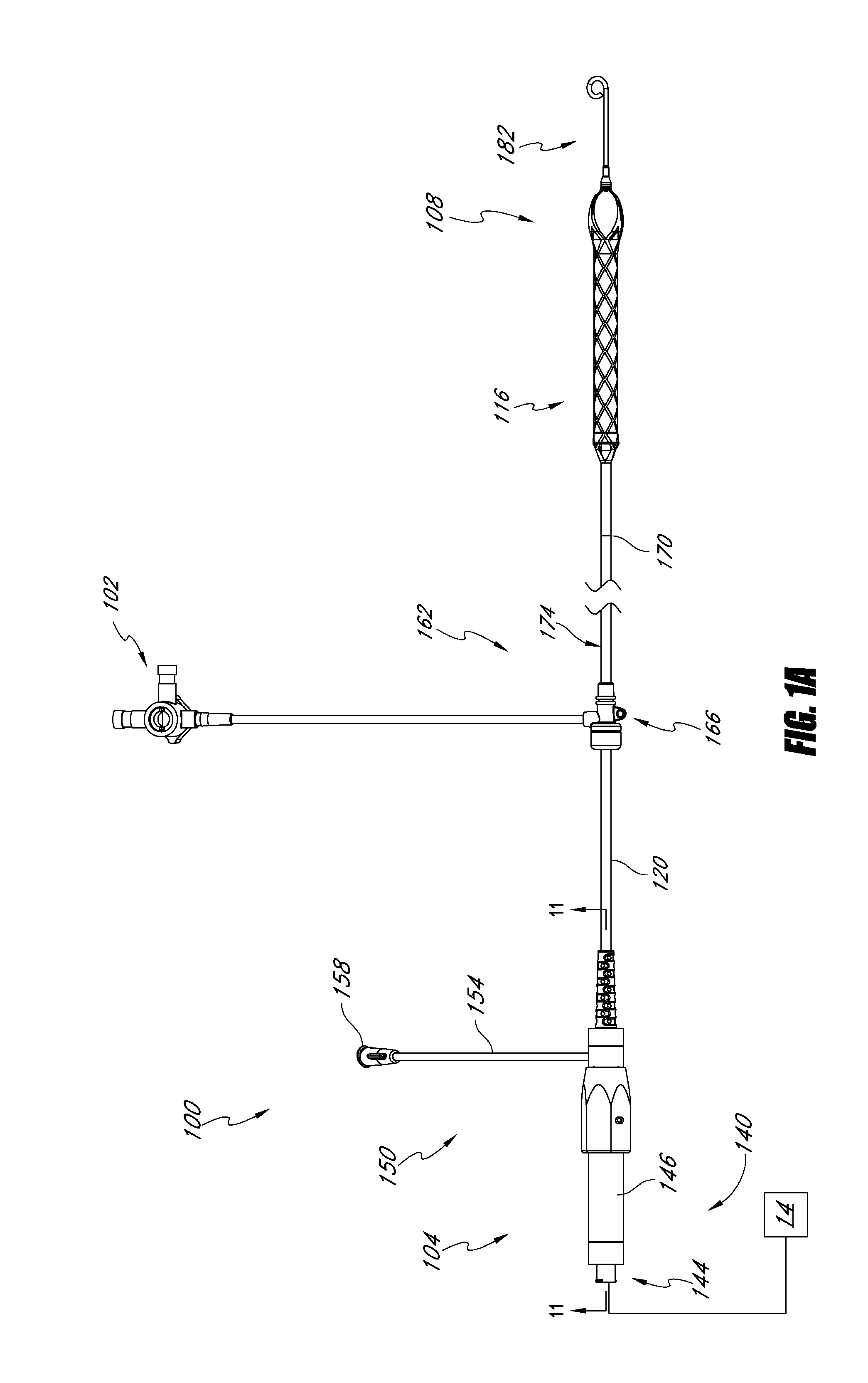
[0037]FIG. 1 illustrates one embodiment of a heart pump 10 that includes a catheter assembly 100 having a proximal end 104 adapted to connect to a motor 14 and a distal end 108 (see FIG. 1A) adapted to be inserted percutaneously into a patient. The motor 14 is connected by a signal line 18 to a control module 22 that provides power and / or control signals to the motor 14. As discussed further below, the heart pump 10 in various embodiments has an i...


PUM


Abstract

Disclosed herein are heart pumps that can include a catheter body and an impeller coupled with a distal end of the catheter body. The impeller can include a tip that is resealable or that includes a resealable member. The heart pump can also include a diffuser disposed between the distal end of the catheter body and the impeller, wherein the diffuser includes a flow directing surface.

Description

CROSS-REFERENCE TO RELATED APPLICATIONS[0001]This application claims priority to U.S. Provisional Application Ser. No. 61 / 430,537 filed Jan. 6, 2011 entitled Percutaneous Heart Pump, which is hereby incorporated by reference herein for all purposes.BACKGROUND OF THE INVENTION[0002]1. Field of the Invention[0003]This application is directed to heart pumps that can be applied percutaneously.[0004]2. Description of the Related Art[0005]Heart disease is a major health problem that claims many lives per year. After a heart attack, only a small number of patients can be treated with medicines or other non-invasive treatment. However, a significant number of patients can recover from a heart attack or cardiogenic shock if provided with mechanical circulatory support.[0006]In a conventional approach, a blood pump having a fixed cross-section is surgically inserted a heart chamber, such as into the left ventricle of the heart and the aortic arch to assist the pumping function of the heart. O...

Claims


Application Information

Patent Timeline
Patent Type & Authority Applications(United States)
IPC IPC(8): A61M1/12A61M60/13A61M60/17A61M60/237A61M60/414A61M60/508A61M60/808A61M60/814A61M60/824
CPCA61M1/101A61M1/1034A61M1/12A61M60/824A61M60/414A61M60/896A61M60/148A61M60/508A61M60/814A61M60/808A61M60/237A61M60/13A61M60/17
Inventor CAMPBELL, ROBERT L.KONCOSKI, JEREMY J.MALLISON, THOMAS M.MCBRIDE, MARK W.METREY, DANIELMYER, ERIC C.POWELL, KEVIN J.ROSLUND, ADAMWALTERS, DANIEL A.REPKA, WILLIAM JAMESYUEN, PHYLLIS
Owner TUBEMASTER INC
Why Eureka
Try Eureka