Gas turbine combustor endcover assembly with integrated flow restrictor and manifold seal

Active Publication Date: 2012-07-19
GENERAL ELECTRIC CO
View PDF10 Cites 35 Cited by
  • Summary
  • Abstract
  • Description
  • Claims
  • Application Information

AI Technical Summary

Benefits of technology

[0007]In a first exemplary embodiment of the invention provides an endcover assembly for a turbine combustor adapted to support one or more combustor nozzles, the endcover assembly comprising a substantially flat plate having one side which in use, faces a combustion chamber and an opposite side which, in use, faces away from the combustion chamber; at least one fuel passage extending through the substantially flat plate; a fuel manifold porting block secured to the opposite side of the flat plate with at least one port aligned with the at least one passage; and a fuel restrictor insert formed with multiple flow orifices located between the flat plate and the fuel manifold porting block in alignment with said at least one fuel passage and the at least one port.
[0008]In another exemplary e

Problems solved by technology

While that change simplified the fuel nozzles and enabled the mounting of a plurality of fuel nozzles onto the endcover, the complexity of the endcover was increased to provide the air and fuel manifolds and necessary multiple passages in

Method used


Image

  • Gas turbine combustor endcover assembly with integrated flow restrictor and manifold seal
  • Gas turbine combustor endcover assembly with integrated flow restrictor and manifold seal
  • Gas turbine combustor endcover assembly with integrated flow restrictor and manifold seal

Examples


Embodiment Construction

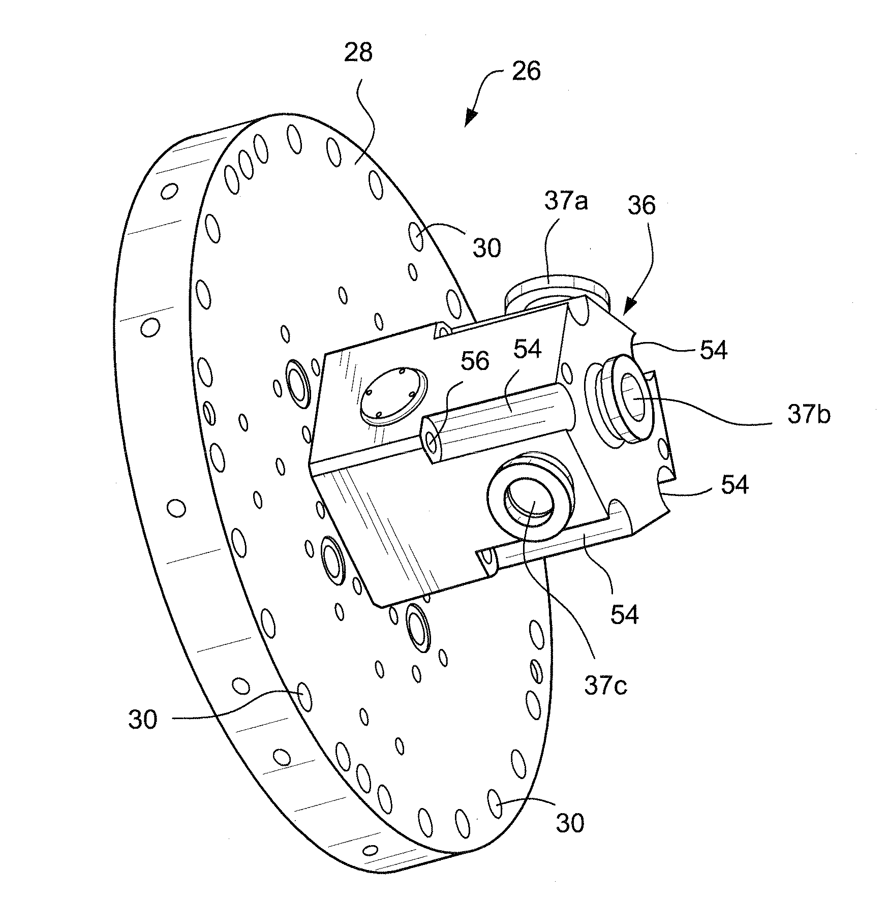
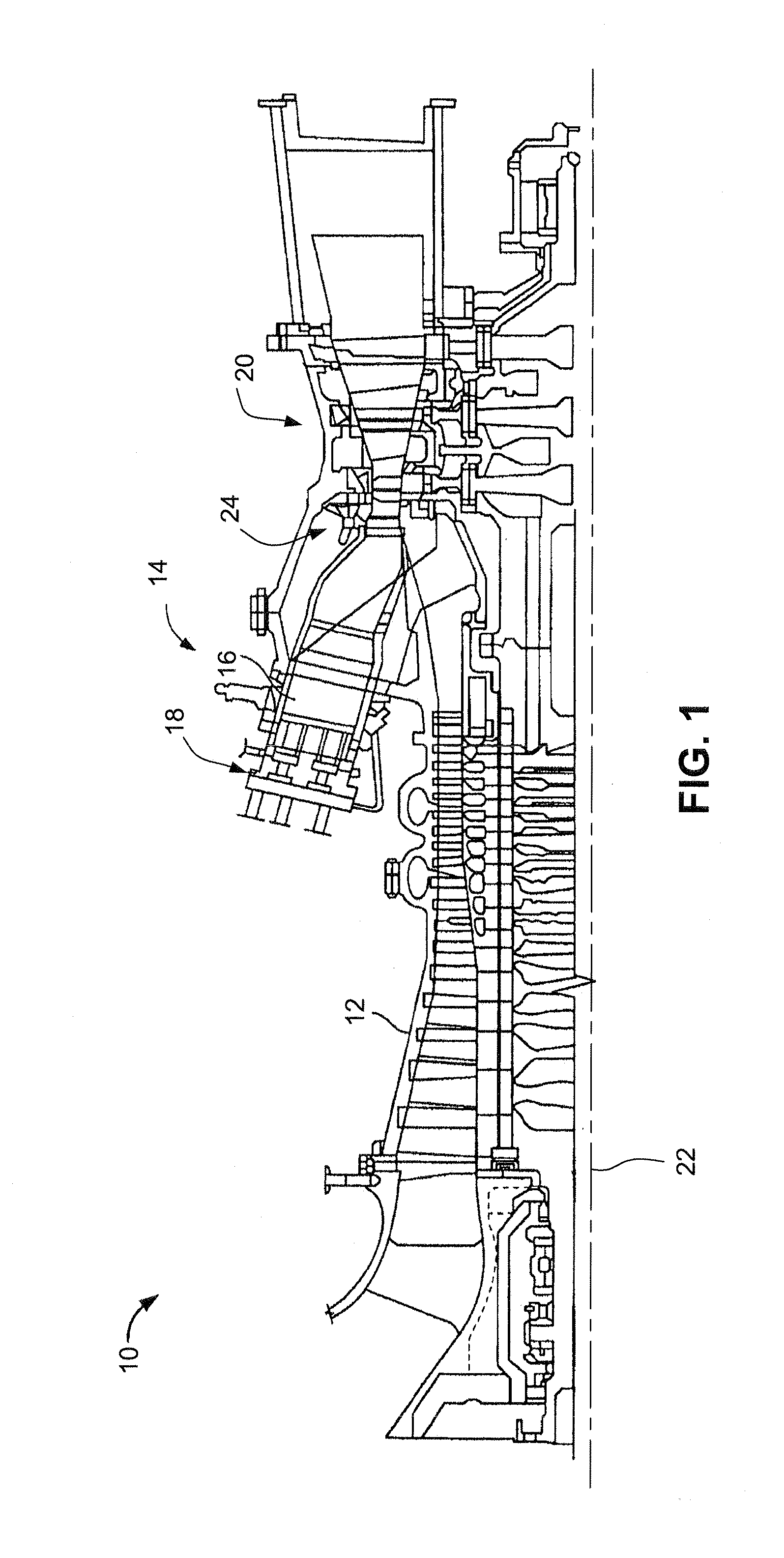
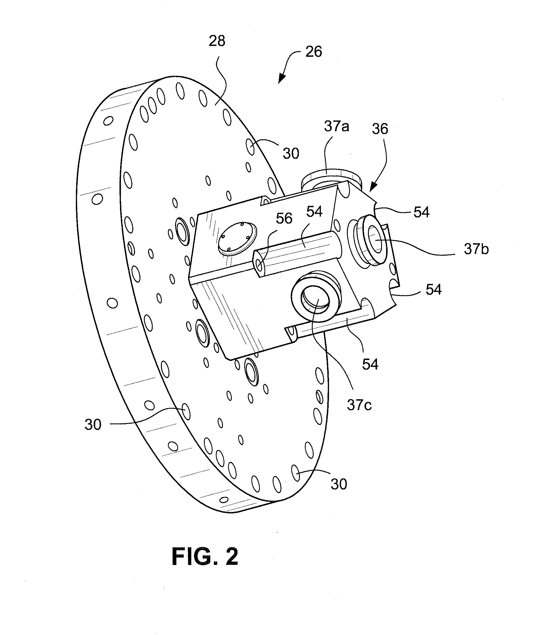
[0018]FIG. 1 is a schematic illustration of an exemplary combustion turbine engine 10. Engine 10 includes a compressor 12 and a combustor 14. Combustor 14 includes a combustion region 16 and a fuel nozzle assembly 18. Engine 10 also includes a turbine 20 and a common compressor / turbine shaft (sometimes referred to as rotor) indicated by the axis 22. In certain turbine engines, there is a plurality of combustors 14 arranged in an annular array about the turbine rotor, all of which supply combustion gases to the turbine first stage 24.

[0019]In operation, air flows through compressor 12 and compressed air is supplied to combustor 14. Specifically, a substantial amount of the compressed air is supplied to fuel nozzle assembly 18 secured to the head end of the combustor 14. Fuel nozzle assembly 18 channels fuel and air to combustion region 16 where the fuel / air is ignited. Combustion gases are supplied to the turbine 20 where the gas stream thermal energy is converted to mechanical rotat...


PUM


Abstract

An endcover assembly for a turbine combustor adapted to support one or more combustor nozzles includes a substantially flat plate having one side which in use, faces a combustion chamber and an opposite side which, in use, faces away from the combustion chamber. At least one fuel passage extends through the substantially flat plate. A fuel manifold porting block is secured to the opposite side of the flat plate with at least one port aligned with the at least one passage. A fuel restrictor insert formed with multiple flow orifices is located between the flat plate and the fuel manifold porting block in alignment with the at least one fuel passage and the at least one port.

Description

BACKGROUND OF THE INVENTION[0001]This invention relates to gas turbine combustors generally, and more specifically, to a novel endcover assembly for the forward or upstream end of a gas turbine combustor.[0002]In certain gas turbines, a plurality of combustors are arranged in an annular array about the turbine rotor to provide for the combustion of fuel and guide the energized combustion products into the turbine section to drive the turbine. Each combustor typically includes an outer casing which defines the external boundary of the combustor, a flow sleeve for distributing compressor discharge air to the head of the combustion system while also cooling a liner which encloses the combustion process, and a transition piece for flowing the combustion products into the turbine section. The combustor also includes a plurality of fuel nozzles coupled to an endcover. Air and fuel is supplied through the endcover to the fuel nozzles for combustion within the liner. The endcover thus funct...

Claims


Application Information

Patent Timeline
IPC IPC(8): F02C7/22
CPCF23K5/14F23K2900/05142F23R2900/00017F23R2900/00012F23R3/283F23R2900/00005
Inventor BAILEY, DONALD MARKLEMON, DONALD TIMOTHYKIM, KWANWOOMELTON, PATRICK BENEDICT
Owner GENERAL ELECTRIC CO
Why Eureka
Try Eureka