Illuminating filter for particle controlled environments

a technology of illumination filter and particle control, applied in the field of filters, to achieve the effect of minimizing negative factors, simplifying the wiring to the lights, and minimizing design and manufacturing errors

Inactive Publication Date: 2012-07-19
OTTESEN LARRY M +1
View PDF3 Cites 5 Cited by
  • Summary
  • Abstract
  • Description
  • Claims
  • Application Information

AI Technical Summary

Benefits of technology

[0027]By combining the filter and illumination segment into one unit, problems associated with the prior art are resolved. Separate filter and light sections are no longer required. Wiring to the lights is simplified. Design and manufacturing errors are minimized.
[0028]In addition to minimizing negative factors inherent in the prior art, the illum...

Problems solved by technology

Because filter media is fragile, the light em...

Method used


Image

  • Illuminating filter for particle controlled environments
  • Illuminating filter for particle controlled environments
  • Illuminating filter for particle controlled environments

Examples


Embodiment Construction

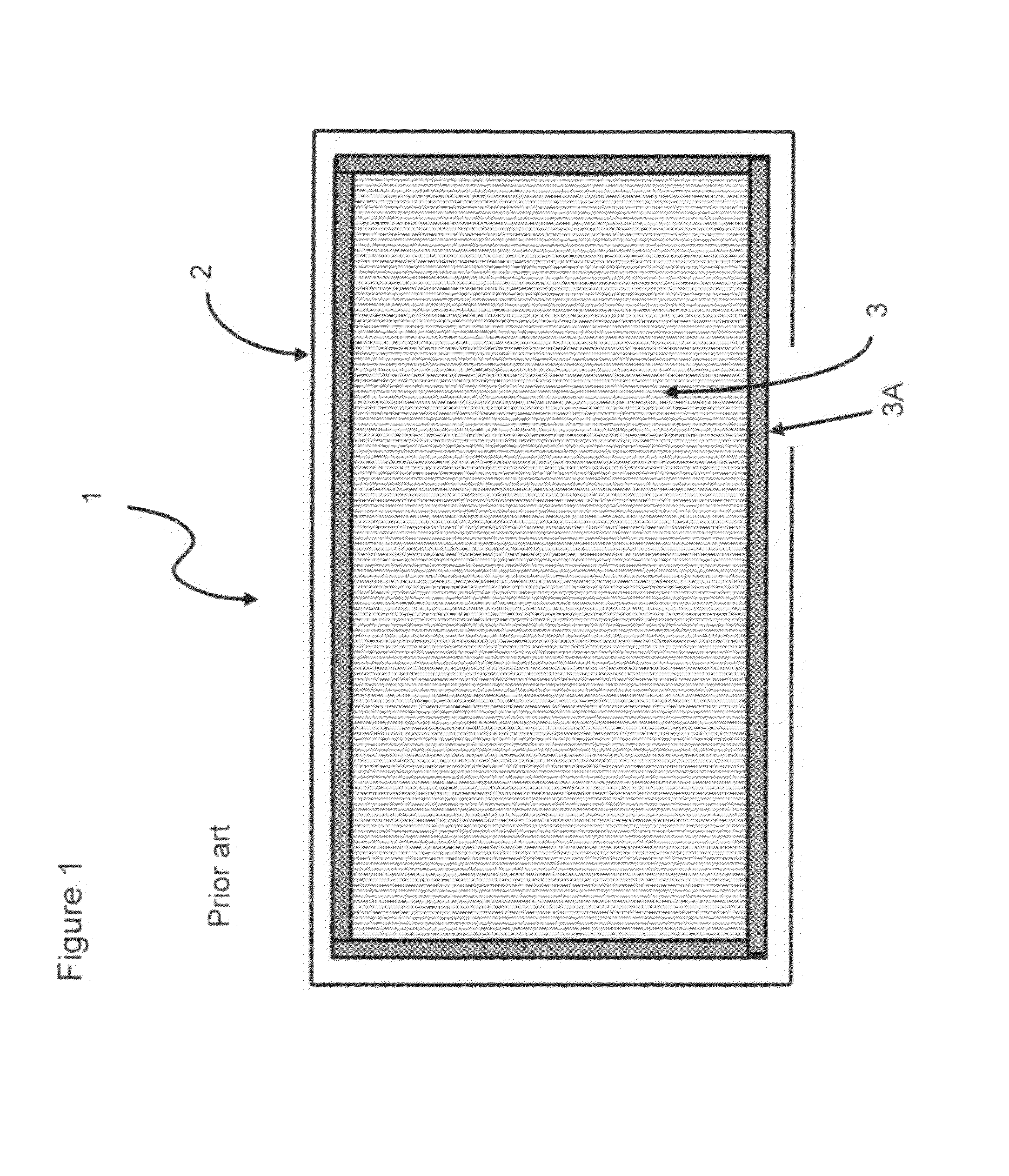
[0049]FIG. 1 shows a prior art air (or gas) filter 1. Filters are used in clean zones, which are categorized into nine classes by ISO Standard 14644. This is a planar view, and the view is perpendicular to the direction of air flow. The filter media 3 removes particles from the air as air passes through the filter media 3. Although filters 1 are discussed in terms of air filtration, filters 1 are also used to filter other gases, such as nitrogen or argon.

[0050]Filter media 3 is fragile, and must be attached to a filter frame 2. This attachment normally utilizes an adhesive seal 3A. Without an adhesive seal 3A, dirty air would bypass the filter media, and the filter would be ineffective. The filter frame 2 provides structural rigidity and support for the filter media 3. When a filter 1 is manually handled, it is picked up with the filter frame 2. Filter frames are typically constructed from passivated metal. For example, aluminum passivated by a layer of aluminum oxide is commonly ch...


PUM

PropertyMeasurementUnit
Lengthaaaaaaaaaa
Volumeaaaaaaaaaa
Electric potential / voltageaaaaaaaaaa

Abstract

An illuminating filter which provides both clean air and light to a particle controlled environment. The integration of filtration and lighting simplifies the design of cleanrooms, mini-environments, and clean zones. Space savings and cost savings are served by combining filtration and lighting into a single structure. Light emitters, such as LEDs or other solid state devices, may be used where low voltage or low current is desirable.

Description

CROSS-REFERENCE TO RELATED APPLICATIONS[0001]This continuation-in-part application claims priority to U.S. Non-provisional application U.S. Ser. No. 12 / 313,531 (confirmation number 2278) filed Nov. 21, 2008 by Larry Ottesen and Jim Harris entitled, “ILLUMINATING FILTER FOR PARTICLE CONTROLLED ENVIRONMENTS”. This application also claims priority to U.S. Provisional Application 61 / 009,893 (confirmation number 6603) filed Jan. 3, 2008 by Larry Ottesen and Jim Harris entitled, “ILLUMINATING FILTER FOR PARTICLE CONTROLLED ENVIRONMENTS”.STATEMENT REGARDING FEDERALLY SPONSORED RESEARCH[0002]Not ApplicableREFERENCE TO A MICROFICHE APPENDIX[0003]Not ApplicableBACKGROUND OF THE INVENTION[0004]1. Field of the Invention[0005]This invention relates to filters which are used to remove particles or airborne molecular contaminants from clean environments. Clean environments include cleanrooms, mini-environments, or controlled work zones as defined by ISO Standard 14644. In particular, the instant i...

Claims


Application Information

Patent Timeline
IPC IPC(8): B01D46/42H05K13/04F24F8/108
CPCB01D46/0005B01D46/42Y10T29/49002F24F3/1603F24F13/078B01D2279/51F24F8/10F24F8/108
Inventor OTTESEN, LARRY M.HARRIS, JAMES M.
Owner OTTESEN LARRY M
Why Eureka
Try Eureka