Cascading once through evaporator

a technology of evaporator and evaporator chamber, which is applied in the direction of steam generation using hot heat carriers, steam separation arrangements, lighting and heating apparatus, etc. it can solve the problems of insufficient supply of liquid, insufficient steam generation of more back positioned heat transfer tubes, and inability to generate enough steam, etc., to achieve simple configuration and less susceptible to overheating and/or failure of components

Active Publication Date: 2012-07-19
NEM ENERGY
View PDF8 Cites 22 Cited by
  • Summary
  • Abstract
  • Description
  • Claims
  • Application Information

AI Technical Summary

Benefits of technology

[0016]It is an object of the present invention to overcome at least one of the above-mentioned drawbacks, at least partially, and / or to provide a useable alternative. In particular, it is an object of the invention to provide a steam generator having an evaporator unit including a conventional heat transfer section with a simple configuration which is less susceptible to overheating and / or failure of components.

Problems solved by technology

A problem relating to this phenomenon is that a more front positioned heat transfer tube may get damaged by overheating while more back positioned heat transfer tubes do not generate sufficient steam.
An additional problem relating especially to the most upstream positioned heat transfer tube, is that the supply of liquid may become too low.
A complete evaporation in one or more of the heat transfer tubes of the evaporator unit may impair stability of operation.
The heat transfer tube may dry out and become overheated which could lead to damages.
However, this proposed solution results in a more complex and large construction of the heat transfer section.
However, also this solution has not appeared to be satisfying.
The configuration of the heat transfer section including a choke device is more complex and susceptible to failures.
A problem to this configuration of the steam generator is that it includes a plurality of throttling means which makes the configuration more complex and susceptible to failures.
Another problem is that the common main separator has a complex configuration including a plurality of inlet ports for connecting the pipes originating from the primary separators.
Another problem of the disclosed steam generator is that a two phase mixture of water and steam is fed downwardly through the temperature stages.
Generated steam tend to rise in the temperature stage which disturbs the evaporating process.
The disclosed steam generator entails stability problems.
Despite of taken measures, it has appeared in practise that it is still a problem to known steam generators that the evaporator unit appears to be susceptible for overheating.
There is still a risk that the front positioned heat transfer tubes deliver a lot of steam and that more back positioned heat transfer tubes in comparison hardly delivers steam.
A major problem is still that, the upper ends of the front positioned heat transfer tubes are susceptible for wear and damage as a result of overheating.
A further problem arises when all heat transfer tubes generate superheated vapour having a steam quality equal or larger than one.
This may cause temperature stratification over the height of the gas conduit.
Heating gas temperature stratification is undesirable because it impairs thermal performance of both the steam generating system itself and possible gas side downstream heat transfer surfaces.

Method used


Image

  • Cascading once through evaporator
  • Cascading once through evaporator

Examples


Embodiment Construction

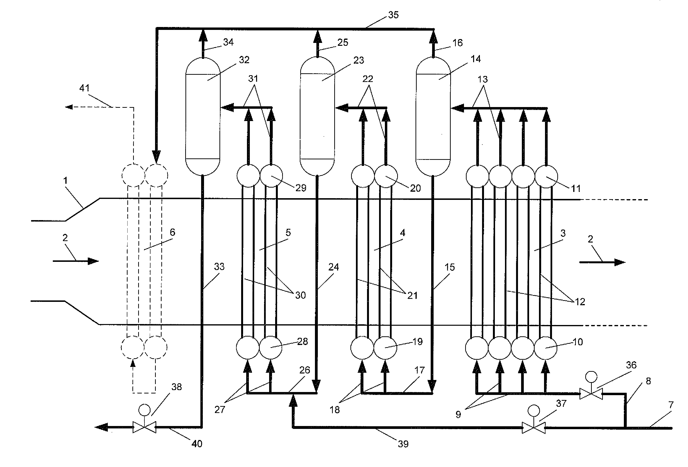
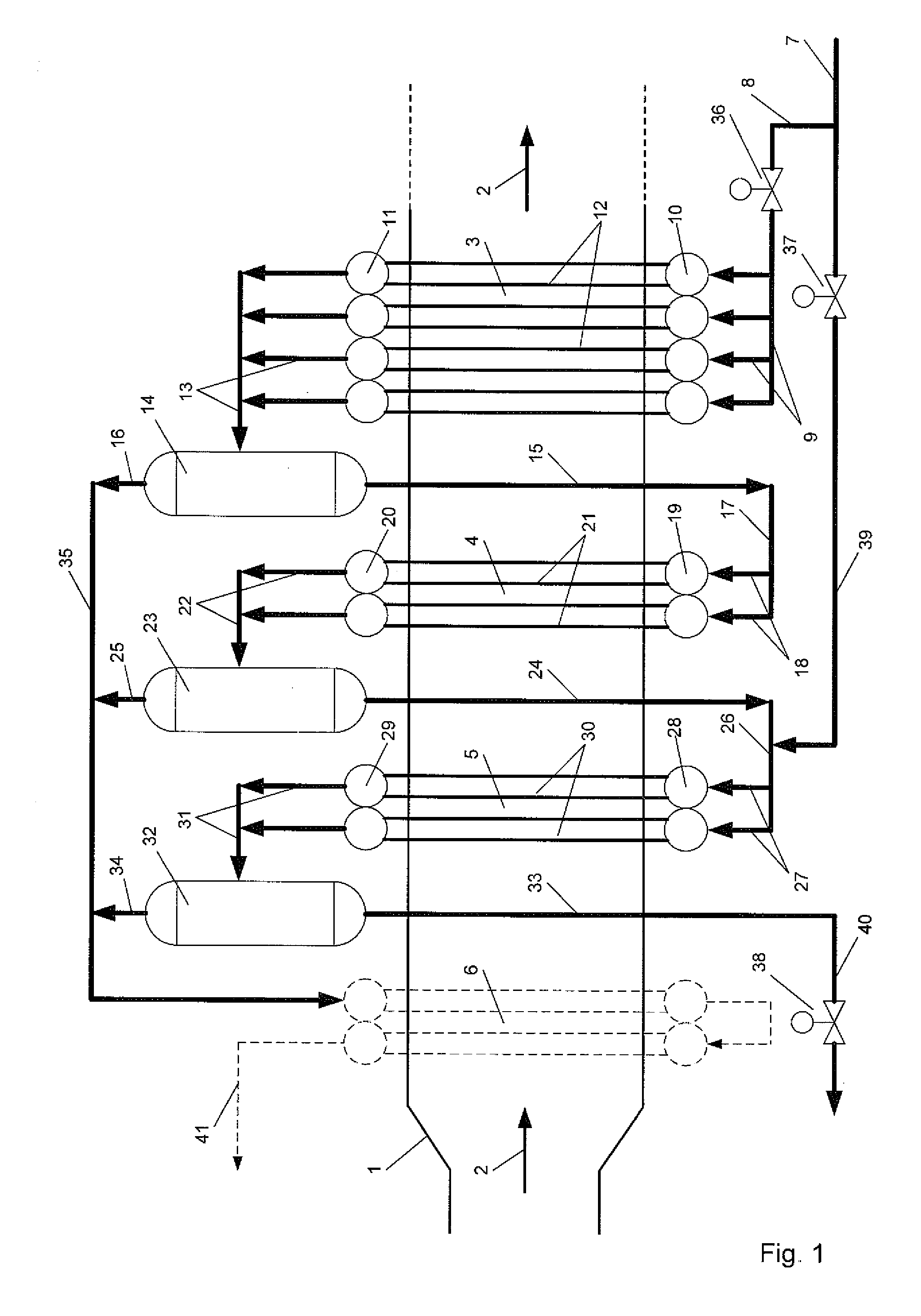
[0046]FIG. 1 shows a diagrammatic representation of a steam generator according to the invention. The steam generator of this embodiment comprises a first, second and third evaporator stage 3, 4 and 5 positioned in cascade in a substantially horizontal gas conduit 1. A heating gas indicated by arrows 2 flows through the gas conduit 1 in a length direction. The first evaporator stage 3 is positioned most downstream the gas flow. A flow medium is supplied by one or more main supply conduits 7. Via one or more first inlet conduits 8, distributing manifolds 9 and distributing headers 10, the flow medium is supplied and distributed to a first heat transfer section 12 of the first evaporator stage 3, which at least partially extend within the gas conduit 1.

[0047]First inlet conduit 8 comprises a control valve 36 to control the flow rate of the flow medium to the first heat transfer section 12 of the first evaporator stage 3.

[0048]The flow medium enters the first heat transfer section 12 i...


PUM


Abstract

A steam generator includes a substantially horizontal gas conduit (1) to guide a heating gas flow (2) and an evaporator unit positioned at least partially in the horizontal gas conduit for transferring heat from the heating gas to a flow medium which flows through the evaporator unit. The heat transfer section of the evaporator unit of the steam generator is bottom fed, which means that the inlet conduit is arranged at a lower region of the heat transfer section. The outlet conduit is arranged at an upper region. The inlet conduit allows an once through operation of the evaporator section which is necessary to enable operation under supercritical circumstances. The evaporator unit includes at least two evaporator stages (3, 4) which are arranged in a cascade. Each evaporator stage includes a heat transfer section (12, 21) and a separator (14, 23). The presence of the separators (14, 23) subdivides the evaporator unit into evaporator stages (3, 4).

Description

CROSS-REFERENCE TO RELATED APPLICATIONS[0001]This application is the National Stage of International Application No. PCT / NL2010 / 050655, filed Oct. 6, 2010, which claims the benefit of Netherlands Application No. 2003596, filed Oct. 6, 2009, and U.S. Provisional Application No. 61 / 248,933, filed Oct. 6, 2009, the contents of all of which are incorporated by reference herein.FIELD OF THE INVENTION[0002]The present invention relates to a steam generator comprising a substantially horizontal gas conduit for guiding a heating gas flow. An evaporator unit is positioned at least partially in the horizontal gas conduit for transferring heat from the gas flow to a flow medium which flows through the evaporator unit. In particular, the steam generator is suitable to operate under both subcritical as supercritical circumstances.BACKGROUND OF THE INVENTION[0003]A steam generator is for example known from WO2007 / 133071 which discloses a single pass evaporator unit which is arranged in a substant...

Claims


Application Information

Patent Timeline
Patent Type & Authority Applications(United States)
IPC IPC(8): F22B1/02
CPCF22B1/18F22B37/26F22B29/062F22B29/06F22B29/064
Inventor ROP, PETER SIMONKRAMER, WALTER ADRIAAN
Owner NEM ENERGY
Why Eureka
Try Eureka