Heat exchange device with confined convective boiling and improved efficiency

a heat exchange device and convective technology, applied in the field of convective and convective boiling heat exchange devices, to achieve the effect of improving the efficiency of the element to be cooled and reducing the heat exchange coefficien

Inactive Publication Date: 2012-07-19
COMMISSARIAT A LENERGIE ATOMIQUE ET AUX ENERGIES ALTERNATIVES
View PDF10 Cites 11 Cited by
  • Summary
  • Abstract
  • Description
  • Claims
  • Application Information

AI Technical Summary

Problems solved by technology

This drying causes a substantial reduction of the heat exchange coefficient, and therefore reduced efficiency of the element to be cooled.

Method used


Image

  • Heat exchange device with confined convective boiling and improved efficiency
  • Heat exchange device with confined convective boiling and improved efficiency
  • Heat exchange device with confined convective boiling and improved efficiency

Examples


Embodiment Construction

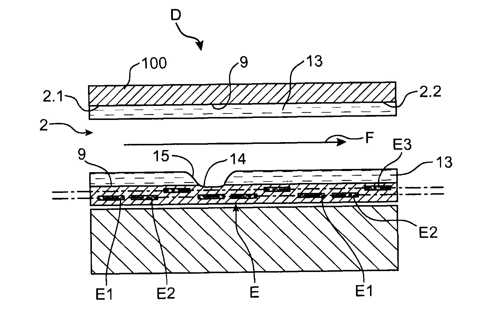
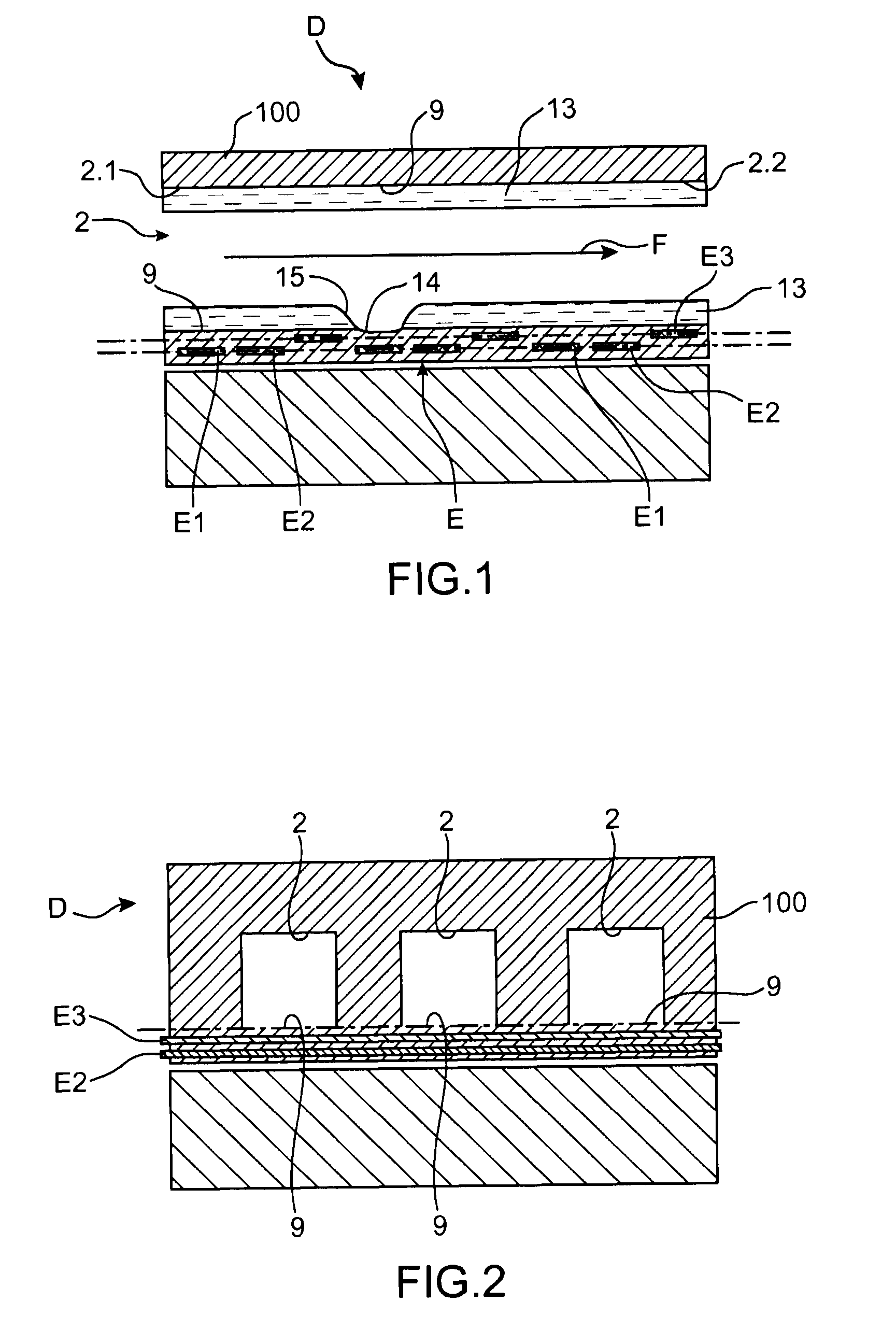
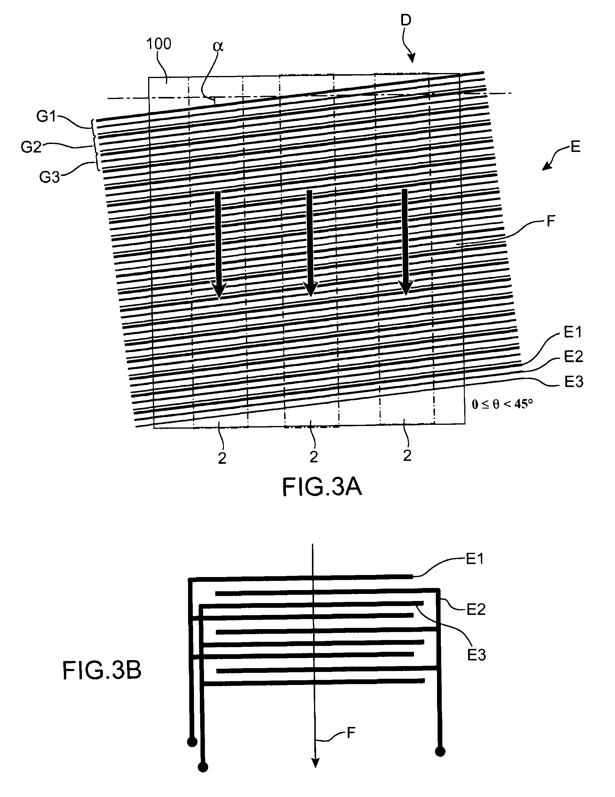
[0005]The previously stated aim is attained through a heat exchange surface in which an electro-wetting device is used to move the drying line in the direction of flow of the liquid, which is formed on the heat exchange surface; thus, by moving this drying line in the liquid's direction of flow the liquid is moved along the wall of the duct, encouraging vapour evacuation.

[0006]Indeed, in convective boiling conditions in a micro-channel the liquid is moved in the micro-channel by convection, for example by means of a pump. At the entrance of the channel the liquid is “cold” and the liquid phase is the predominant phase.

[0007]Vapour bubbles are formed on the surface of the micro-channel. These increase in number. They coalesce until they fill the centre of the micro-channel. Only a film of liquid remains on the wall of the channel. Vapour is then the predominant phase. And cooling takes place by dissipation of the vapour formed in this manner, which is accomplished in a forced fashion...


PUM

PropertyMeasurementUnit
frequencyaaaaaaaaaa
frequencyaaaaaaaaaa
γaaaaaaaaaa

Abstract

A heat exchange device with convective and confined boiling includes a channel in a substrate in contact with an element to be cooled, in which a polar fluid flows from upstream to downstream, a mechanism of movement of the fluid by convection in the channel imposing a direction of flow, and a device for movement by electro-wetting positioned between the channel and the element to be cooled to move the fluid in the channel. The channel includes an inner surface having low wettability with regard to the polar fluid. The mechanism of movement by electro-wetting includes electrodes and a controller to apply selectively a potential to the electrodes such that an electrostatic force gradient is applied to the fluid in the direction of flow.

Description

TECHNICAL FIELD AND PRIOR ART[0001]The present invention relates to a heat exchange device with convective and confined boiling and improved efficiency, which can be used for cooling electronic components and components dissipating heat energy.[0002]The phenomenon of boiling is very often used in heat exchange devices; one of the types of boiling conditions used is convective and confined boiling: in these conditions the liquid flows in a pipe of hydraulic diameter less than the capillary length of said liquid.[0003]The bubbles are generally formed upstream, in the channel's first hot zones, above a critical temperature threshold. Subsequently, through a confinement effect, they are crushed and coalesce to form vapour locks. The heat is then principally transmitted through a micro-layer of liquid which is in contact with the wall of the channel. When heat transfer occurs in confined spaces a premature drying of the walls of the channel is generally observed. This drying causes a sub...

Claims


Application Information

Patent Timeline
Patent Type & Authority Applications(United States)
IPC IPC(8): F28D15/00H05K13/00F28F27/00
CPCF28F13/16F28F13/18F28F13/182F28F13/185H01L23/473H01L2924/0002F28F2245/04H01L2924/00
Inventor GAVILLET, JEROMEPHAN, HAI TRIEU
Owner COMMISSARIAT A LENERGIE ATOMIQUE ET AUX ENERGIES ALTERNATIVES
Why Eureka
Try Eureka