Synchronous reluctance machine

a synchronous and synchronous technology, applied in the direction of magnetic circuit rotating parts, electric generator control, shape/form/construction, etc., can solve the problems of complex manufacturing low power factor, and low so as to increase the efficiency of synchronous reluctance machines

Active Publication Date: 2021-01-26
FLENDER GMBH
View PDF37 Cites 0 Cited by
  • Summary
  • Abstract
  • Description
  • Claims
  • Application Information

AI Technical Summary

Benefits of technology

[0029]Thus, both the rotor and the laminated core of the stator are cooled efficiently. On the back of the laminated stator core, i.e. on the outer side of the stator—if the synchronous reluctance machine is embodied as an internal rotor—the cooling air can be collected and conveyed to one or both exhaust-air side winding heads, wherein on the way thereto and / or therefrom, the heated cooling air flow is cooled back down by means of a heat exchanger.
[0030]With this inventive reluctance machine, it is in principle advantageous for at least part of the cooling air that has been cooled back down by the heat exchanger to be conveyed directly to the rotor and hence also to the permanent magnets. This avoids premature heating of this re-cooled cooling air due to stator losses. As a result, the permanent magnets are optimally cooled thus further increasing the efficiency of this reluctance machine.

Problems solved by technology

However, such machines have a rotor that is complex to manufacture with a squirrel cage or a pole winding.
Machines in this power class generally require the rotor to be cooled since the losses arising there are no longer able to be dissipated solely by convection.
Compared to the machines mentioned above, a synchronous reluctance machine has the drawback that the power factor is relatively low—about 0.7 to 0.75.
This type of cooling is inter alia not suitable for machines with a greater power since the ratio of volume to surface is too low and thus no sufficient cooling surface is available.

Method used


Image

  • Synchronous reluctance machine
  • Synchronous reluctance machine
  • Synchronous reluctance machine

Examples


Embodiment Construction

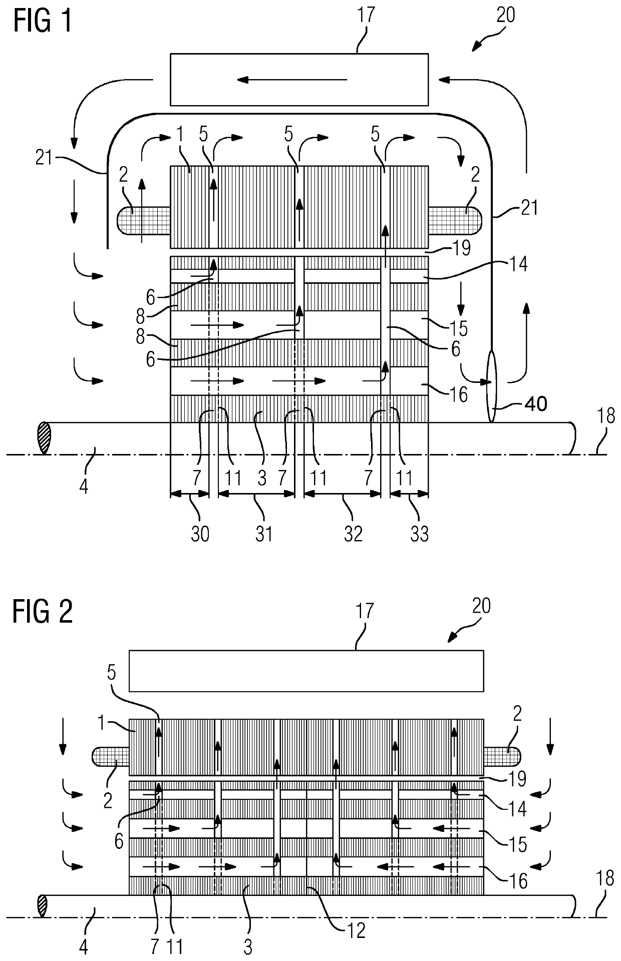
[0042]FIG. 1 shows, in a part longitudinal section, a synchronous reluctance machine 20 comprising a stator 1 with a winding head 2 on each of its axial end faces each of which winding heads belongs to a winding system, not shown in greater detail, which is embedded in substantially axially extending grooves of the stator 1.

[0043]The stator 1 is spaced apart from a rotor 3 by an air gap 19, wherein the rotor 3 is connected in a torsion-proof manner to a shaft 4 and mounted rotatably about an axis 18.

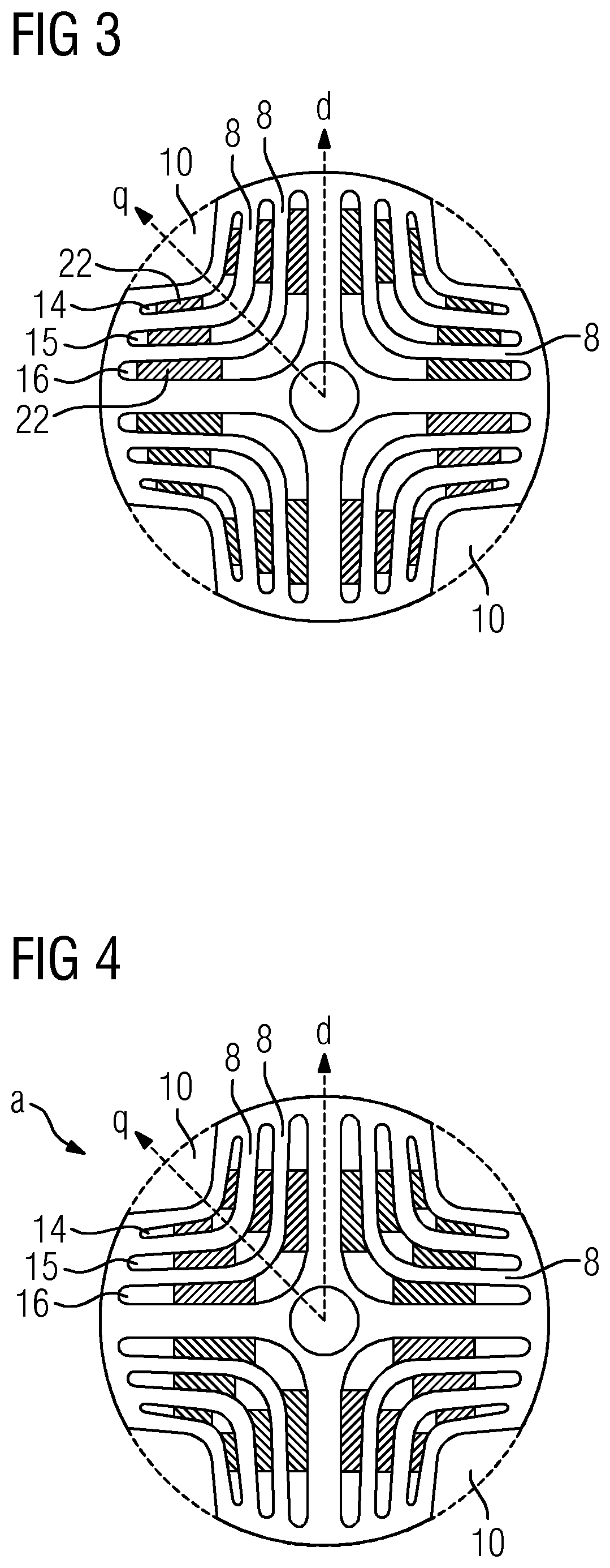
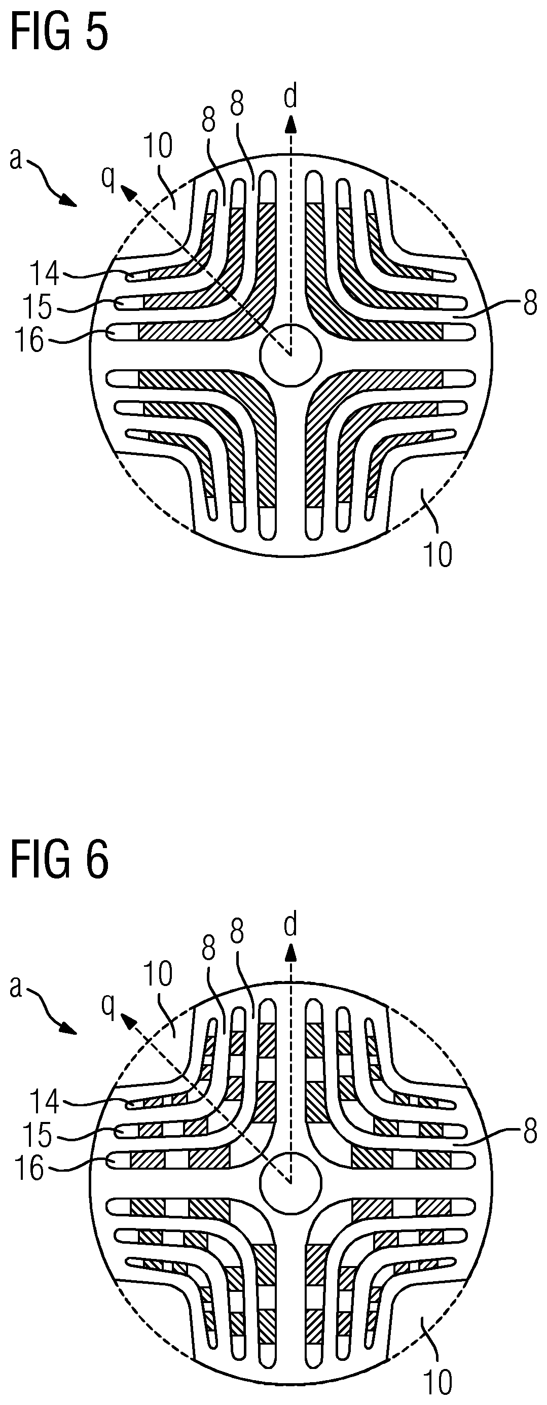
[0044]The rotor 3 is embodied as a four-pole reluctance rotor, wherein, as viewed in the circumferential direction, flux blocking sections 14, 15, 16 and intermediate flux conducting sections 8 form four poles. In this exemplary embodiment, viewed in the radial direction, three flux blocking sections 14, 15, 16 are present.

[0045]The inventive concept is not restricted to a four-pole synchronous reluctance machine 20 but can also be transferred to two-pole, six-pole, eight-pole machines e...


PUM


Abstract

A synchronous reluctance machine includes a stator and a rotor spaced apart from the stator by an air gap. The rotor is rotatably mounted about an axis and has laminations arranged axially behind one another. Each lamination has an anisotropic magnetic structure formed by flux blocking sections and flux conducting sections, wherein the flux blocking sections and the flux conducting sections form poles of the rotor. The flux blocking sections form axial channels, wherein in at least some flux blocking sections permanent magnets are provided that do not completely occupy the respective flux blocking section and thus allow axial airflow in all flux blocking sections. The laminated core of the rotor is axially subdivided into at least two component laminated cores, with radial cooling gaps formed between the poles in the region of the q axis as viewed in circumferential direction and between the component laminated cores as viewed axially.

Description

CROSS-REFERENCES TO RELATED APPLICATIONS[0001]This application is the U.S. National Stage of International Application No. PCT / EP2018 / 055009, filed Mar. 1, 2018, which designated the United States and has been published as International Publication No. WO 2018 / 172033 A1 and which claims the priority of European Patent Application, Serial No, 17162103.0, filed Mar. 21, 2017, pursuant to 35 U.S.C. 119(a)-(d).BACKGROUND OF THE INVENTION[0002]The invention relates to a synchronous reluctance machine. In particular a motor or a generator of a wind power plant comprising a stator and a rotor, which is spaced apart from said stator by an air gap and which is rotatably mounted about an axis, with an anisotropic magnetic structure formed by flux blocking sections arranged substantially axially one behind the other.[0003]The invention also relates to a wind power plant with a generator embodied in this manner.[0004]As a rule, asynchronous machines with squirrel cage rotors or synchronous mach...

Claims


Application Information

Patent Timeline
Patent Type & Authority Patents(United States)
IPC IPC(8): F03D9/00H02P9/04H02K1/32F03D9/25F03D80/60F03D80/80H02K1/24H02K7/18
CPCH02K1/325F03D9/25F03D80/60F03D80/80H02K1/246H02K7/1838H02K1/2766H02K1/32H02K9/06Y02E10/72
Inventor ZEICHFÜSSL, ROLAND
Owner FLENDER GMBH
Why Eureka
Try Eureka