Moment limiting control laws for dual rigid rotor helicopters

a control law and rigid rotor technology, applied in the field of helicopters, can solve problems such as control problems and problems with clearance between the dual rotors

Active Publication Date: 2012-07-19
SIKORSKY AIRCRAFT CORP
View PDF3 Cites 19 Cited by
  • Summary
  • Abstract
  • Description
  • Claims
  • Application Information

AI Technical Summary

Benefits of technology

[0012]FIG. 4 is a schematic of an embodiment of a control system for a helicopter;
[0013]FIG. 5 is a schematic of a schematic of control param

Problems solved by technology

The rotor moments lead to control problems with the helicopter,

Method used


Image

  • Moment limiting control laws for dual rigid rotor helicopters
  • Moment limiting control laws for dual rigid rotor helicopters
  • Moment limiting control laws for dual rigid rotor helicopters

Examples


Embodiment Construction

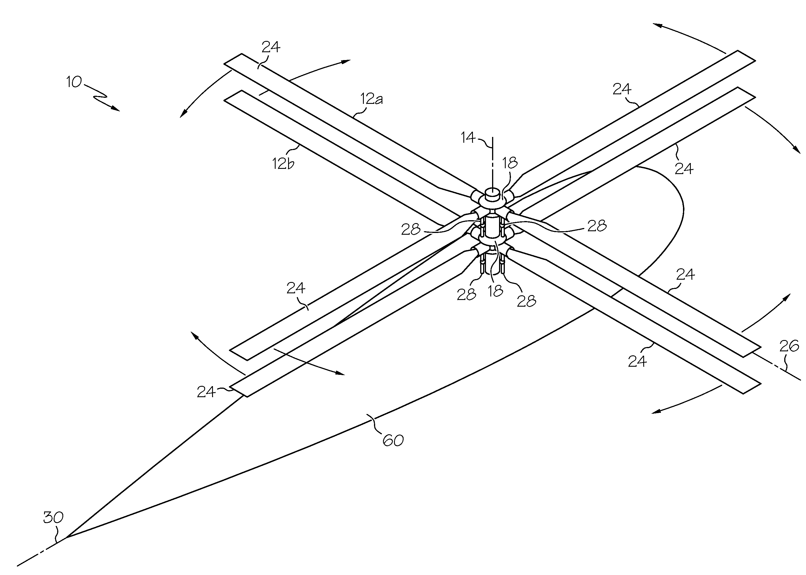
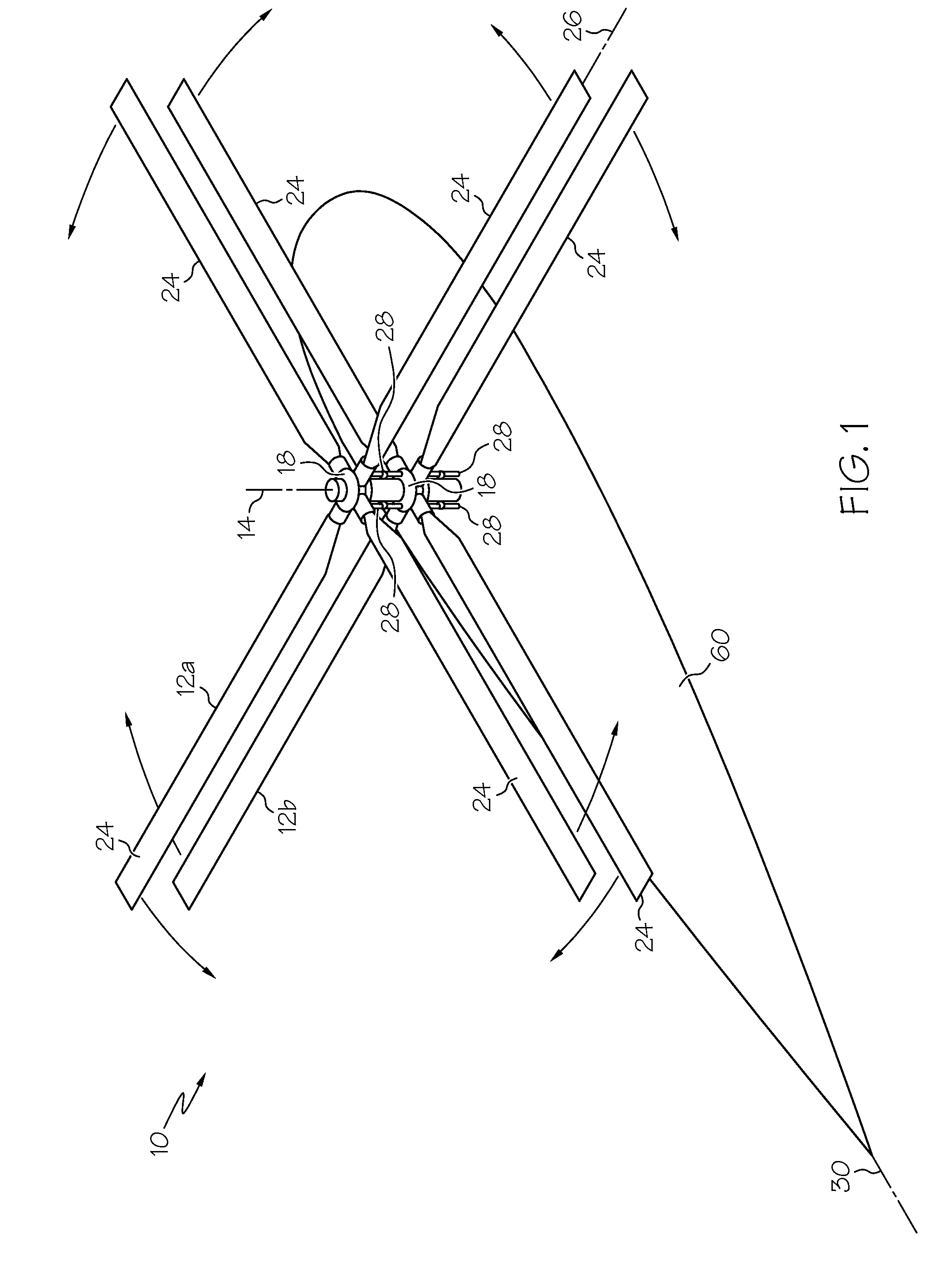
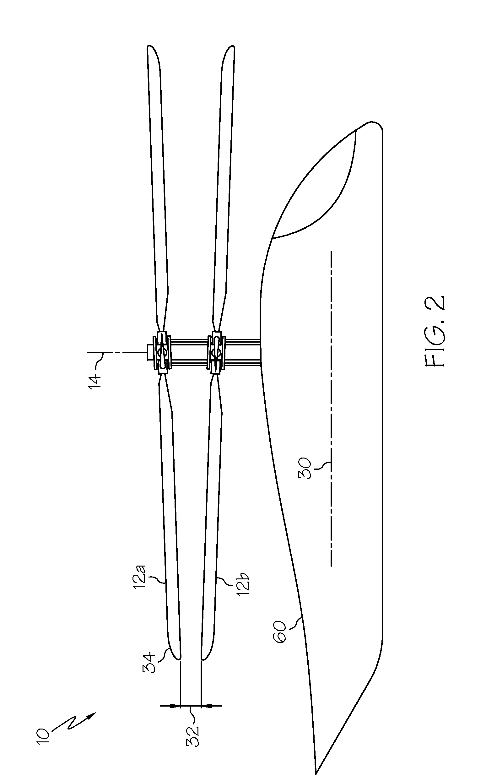
[0016]Shown in FIG. 1 is a schematic of an embodiment of a dual rotor helicopter 10. The helicopter 10 includes an airframe 60 and two rotors 12a and 12b arranged concentrically at the airframe 60 at a rotor axis 14. The rotors 12a and 12b are counterrotating such that, for example, when viewed from above, rotor 12a rotates in a counterclockwise direction and rotor 12b rotates in a clockwise direction. It is to be appreciated that, in other embodiments, the directions of rotation of the rotors 12a and 12b may be reversed. Each of the rotors 12a and 12b is connected to a conventional swashplate 18 so that motion of the swashplate 18 along the rotor axis 14 will cause the blades 24 to vary pitch collectively relative to a blade axis 26 and tilting of the swashplate 18 relative to the axis 14 will cause the blades 24 to pitch cyclically relative to the blade axis 26. The swashplate 18 is driven by one or more control servos 28 to move and / or tilt the swashplate 18 with respect to the r...


PUM


Abstract

A method of counteracting a rotor moment of one or more rotors of a concentric dual-rotor helicopter includes sensing angular velocity and angular acceleration of a helicopter during a flight maneuver. The angular velocity and angular acceleration are compared to a set of control parameters and one or more control servos change the cyclic pitch of the one or more rotors to counteract the rotor moment. A control system for counteracting a rotor moment of one or more rotors of a concentric dual-rotor helicopter includes one or more sensors configured to sense angular velocity and angular acceleration of a helicopter during a flight maneuver. A computer is operably connected to the one or more sensors and configured to compare sensor data to a set of control parameters. A plurality of control servos change the cyclic pitch of the one or more rotors to counteract the rotor moment.

Description

CROSS REFERENCE TO RELATED APPLICATIONS[0001]This application claims priority to U.S. provisional application 61 / 432,851 filed Jan. 14, 2011, the entire contents of which are incorporated herein by reference.BACKGROUND OF THE INVENTION[0002]The subject matter disclosed herein relates to helicopters. More specifically, the subject disclosure relates to control and reduction of rotor moments in dual-rotor helicopters.[0003]Dual rotor helicopeters are those with two coaxial, counterrotating rotors. During helicopter maneuvers, rotor moments acting on each rotor are produced which are equal to the rotor mass moment of inertia, times the rotor angular velocity, times the helicopter angular velocity. This rotor moment is produced at a right angle to the aircraft angular velocity in the direction of rotor rotation, and the rotor moments acting on each rotor are substantially opposing. For example, a helicopter helicopter roll rate produces opposing rotor pitch moments in the rotors and a h...

Claims


Application Information

Patent Timeline
IPC IPC(8): G05D1/00B64C11/28B64C27/54B64C27/00
CPCB64C27/10B64C27/04
Inventor ELLER, EREZKNAG, JOHN
Owner SIKORSKY AIRCRAFT CORP
Why Eureka
Try Eureka