Display device

a display device and display technology, applied in the field of display devices, can solve the problems of complicated control of electronic equipment, increased size of electronic equipment, narrow display area, etc., and achieve the effect of high general versatility and high operability

Active Publication Date: 2012-07-19
JAPAN DISPLAY INC
View PDF4 Cites 42 Cited by
  • Summary
  • Abstract
  • Description
  • Claims
  • Application Information

AI Technical Summary

Benefits of technology

[0009]In electronic equipment having a display device with a touch panel in the related art, for example, mechanical switches, such as membrane switches, are arranged outside a display area, and an operation relating to a frequently used function or a specific operation is assigned to the mechanical switch in some cases. By doing this, for example, invoking of a frequently used function or a specific operation can be directly performed irrespective of contents displayed on a display panel, improving operability.
[0013]It is an object of the invention to provide a display device with a touch panel which can, for example, achieve compatibility between the simplicity of the configuration or control of electronic equipment and the maintaining of its high operability.
[0014]It is another object of the invention to provide a display device with a touch panel which can, for example, suppress a reduction in general versatility when being incorporated into electronic equipment.
[0027]By using the display device according to the invention, it is possible to achieve compatibility between the simplicity of the configuration or control of electronic equipment having the display device with the touch panel and the maintaining of its high operability.
[0028]Moreover, the display device according to the invention has high general versatility when being incorporated into electronic equipment.

Problems solved by technology

However, when the mechanical switch is arranged, there arises a problem that the configuration or control of the electronic equipment is complicated by the amount corresponding to the arrangement.
Moreover, when the mechanical switch is arranged, a space for arranging the switch is needed outside the display area.
Therefore, there arises a problem that the electronic equipment is increased in size or the display area is narrowed.

Method used


Image

  • Display device
  • Display device
  • Display device

Examples


first embodiment

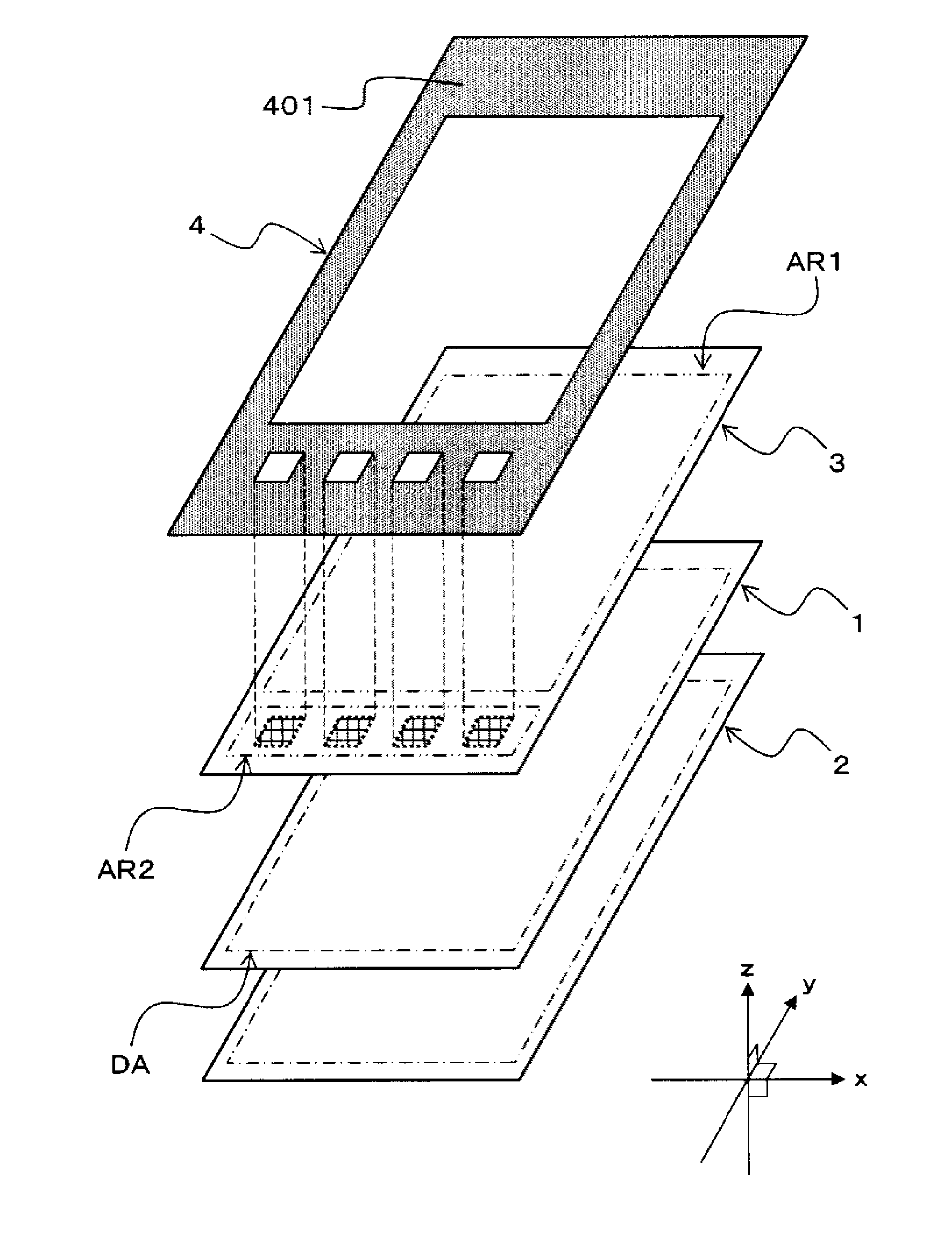
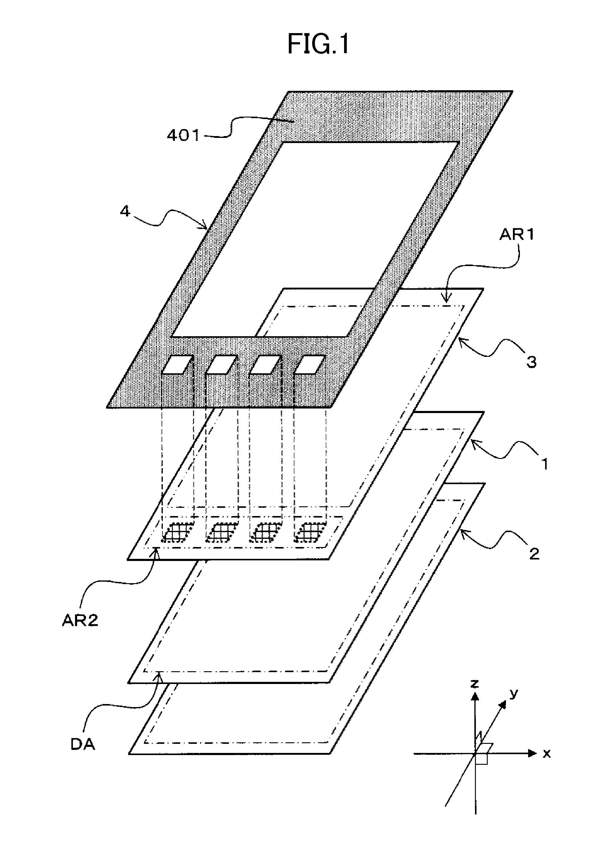
[0037]FIGS. 1 to 3 are schematic views showing a schematic configuration of a display device with a touch panel of a first embodiment according to the invention.

[0038]FIG. 1 is a schematic exploded perspective view showing an example of a main portion in the display device with the touch panel of the first embodiment. FIG. 2 is a schematic side view of the display device with the touch panel shown in FIG. 1. FIG. 3 is a schematic plan view showing an example of a touch panel in the display device with the touch panel of the first embodiment.

[0039]FIG. 2 shows a side view along the yz plane in an xyz orthogonal coordinate system shown in FIG. 1. FIG. 3 is a plan view along the xy plane in the xyz orthogonal coordinate system shown in FIG. 1. In the xyz orthogonal coordinate system shown in FIG. 1, the xy plane is parallel with a display surface (display area) in a display panel, and a viewer observes the display device mainly from the +z-axis direction side.

[0040]In the first embodim...

second embodiment

[0055]FIGS. 4 and 5 are schematic views showing a schematic configuration of a display device with a touch panel of a second embodiment according to the invention.

[0056]FIG. 4 is a schematic plan view showing an example of a planar configuration of the touch panel in the display device with the touch panel of the second embodiment. FIG. 5 is a schematic side view of the display device with the touch panel of the second embodiment.

[0057]FIG. 4 shows the plan view along the xy plane in the xyz orthogonal coordinate system shown in FIG. 1. FIG. 5 shows the side view along the yz plane in the xyz orthogonal coordinate system shown in FIG. 1.

[0058]Also in the second embodiment, a liquid crystal display device having a touch panel disposed therein is taken as an example of a display device with a touch panel according to the invention. In this case, the display device has, for example as shown in FIG. 1, the liquid crystal display panel 1, the backlight 2, the touch panel 3, and the front...

third embodiment

[0067]FIG. 6 is a schematic plan view showing an example of a touch panel in a display device with a touch panel of a third embodiment according to the invention.

[0068]FIG. 6 shows a plan view along the xy plane in the xyz orthogonal coordinate system shown in FIG. 1.

[0069]The first and second embodiments describe, as an example, the case where the planar shape and arrangement rule of the electrodes in the first detection area AR1 are the same as those of the second detection area AR2. However, when the second detection area AR2 is used for operation buttons, it is sufficient that the presence or absence of touch to an area to be used as an operation button can be detected in the second detection area AR2. Therefore, when the second detection area AR2 is used for operation buttons, the detection accuracy required for the second detection area AR2 is relatively low. Accordingly, when the second detection area AR2 is used for operation buttons, electrodes to be disposed in the second ...


PUM


Abstract

A display device which can achieve compatibility between the simplicity of the configuration or control of electronic equipment and the maintaining of its high operability includes: a display panel and a touch panel arranged on a front surface side of the display panel as viewed from a viewer. The touch panel includes one transparent substrate and a conductive pattern disposed on the substrate. A plurality of detection areas in each of which a touch position can be detected are provided in the touch panel. A non-detection area in which the touch position is not detected is provided between two detection areas next to each other.

Description

CROSS-REFERENCE TO RELATED APPLICATION[0001]The present application claims priority from Japanese application JP 2011-007840 filed on Jan. 18, 2011, the content of which is hereby incorporated by reference into this application.BACKGROUND OF THE INVENTION[0002]1. Field of the Invention[0003]The present invention relates to a display device, and more particularly, to a technique effectively applied to a liquid crystal display device having a touch panel arranged on a liquid crystal display panel.[0004]2. Description of the Related Art[0005]Examples of display devices in the related art include a display device having a man-machine interface called a touch panel arranged on a display panel (hereinafter referred to as display device with a touch panel). The display device with the touch panel is being widely used for, for example, bank s ATMs (Automatic Teller Machines), car navigation systems, mobile-phone handsets, and the like.[0006]The touch panel is generally disposed such that an...

Claims


Application Information

Patent Timeline
Patent Type & Authority Applications(United States)
IPC IPC(8): G06F3/045G06F3/041
CPCG06F3/03547G06F2203/0339G06F3/044G06F3/0443G06F3/0446G06F3/0418G06F3/0412G06F2203/04103G06F2203/04107G06F2203/04111
Inventor KUBO, MASAKINISHITANI, SHIGEYUKI
Owner JAPAN DISPLAY INC
Why Eureka
Try Eureka