Printing Quality Evaluation System, Laser Marking Apparatus, Printing Condition Setting Device, Printing Quality Evaluation Apparatus, Printing Condition Setting Program, Printing Quality Evaluation Program, And Computer-Readable Recording Medium

a printing quality evaluation and laser marking technology, applied in recording devices, instruments, thermography, etc., can solve the problems of hardly performing visual check, barcode reader hardly reading the code print, and small size of printed symbols, so as to improve printing quality, evaluate printing quality of symbols, and enhance printing quality

Inactive Publication Date: 2012-07-19
KEYENCE
View PDF4 Cites 38 Cited by
  • Summary
  • Abstract
  • Description
  • Claims
  • Application Information

AI Technical Summary

Benefits of technology

[0014]According to a still another embodiment of the invention, a laser marking apparatus that can print plural symbols having different printing conditions in a printing target, the laser marking apparatus includes: a parameter setting section that can set at least one printing parameter to a variable parameter varying the printing condition in plural printing parameters constituting the printing conditions, and sets other printing parameters to fixed parameters; a printing condition generating section that substitutes plural different parameter values for the variable parameter set by the parameter setting section while substituting fixed values for the fixed parameters set by the parameter setting section, thereby generating the plural different printing conditions; a printing data generation section that causes a printing quality evaluation apparatus to read different piece of identification information, and sets the identification information to an identifiable symbol to generate printing data, the identification information identifying at least information on the variable parameter included in the printing condition, the identification information being previously correlated with each of the plural different printing conditions generated by the printing condition generating section; and a marking section that prints the plural different symbols generated by the printing data generation section based on each printing condition correlated with the identification information included in the symbol, wherein the printing condition is identified in printing the symbol based on the identification information that is evaluated as the high printing quality by the printing quality evaluation apparatus in the plural printed symbols, and the printing condition can be reflected on next printing. The identification information identifying the printing condition is included in each of the plural different symbols while being able to be read with the printing quality evaluation apparatus, which allows the recognition of the identification information corresponding to the symbol that is evaluated as the high printing quality by the printing quality evaluation apparatus side. As a result, the printing condition can be set by feeding back the identification information to the laser marking apparatus such that the read stability of the optical information reading apparatus is improved during the operation. Therefore, the setting of the proper printing condition can qualitatively be set irrespective of the visual checking or experience of the user.

Problems solved by technology

However, in the above technologies, the symbol in which the desired result is obtained is selected from the plural actually-printed symbols (for example, a QR code) by visual checking of the user, which results in a problem in that the visual checking is hardly performed when the size of the printed symbol becomes significantly small.
Accordingly, even in the code print that is determined to be successful by the visual checking of the user, possibly the barcode reader hardly reads the code print.

Method used


Image

  • Printing Quality Evaluation System, Laser Marking Apparatus, Printing Condition Setting Device, Printing Quality Evaluation Apparatus, Printing Condition Setting Program, Printing Quality Evaluation Program, And Computer-Readable Recording Medium
  • Printing Quality Evaluation System, Laser Marking Apparatus, Printing Condition Setting Device, Printing Quality Evaluation Apparatus, Printing Condition Setting Program, Printing Quality Evaluation Program, And Computer-Readable Recording Medium
  • Printing Quality Evaluation System, Laser Marking Apparatus, Printing Condition Setting Device, Printing Quality Evaluation Apparatus, Printing Condition Setting Program, Printing Quality Evaluation Program, And Computer-Readable Recording Medium

Examples


first embodiment

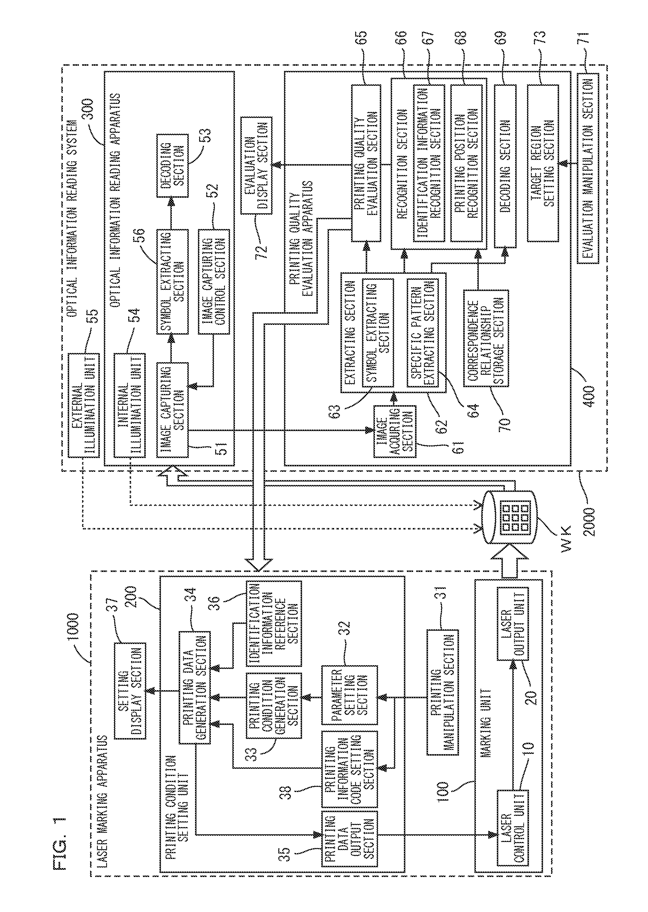
[0120]FIG. 1 is a block diagram illustrating a printing quality evaluation system according to a first embodiment of the invention. The printing quality evaluation system of FIG. 1 includes a laser marking apparatus 1000 that prints a symbol to a workpiece WK of a printing target and an optical information reading system 2000 that reads the printed symbol to evaluate printing quality.

(Laser Marking Apparatus 1000)

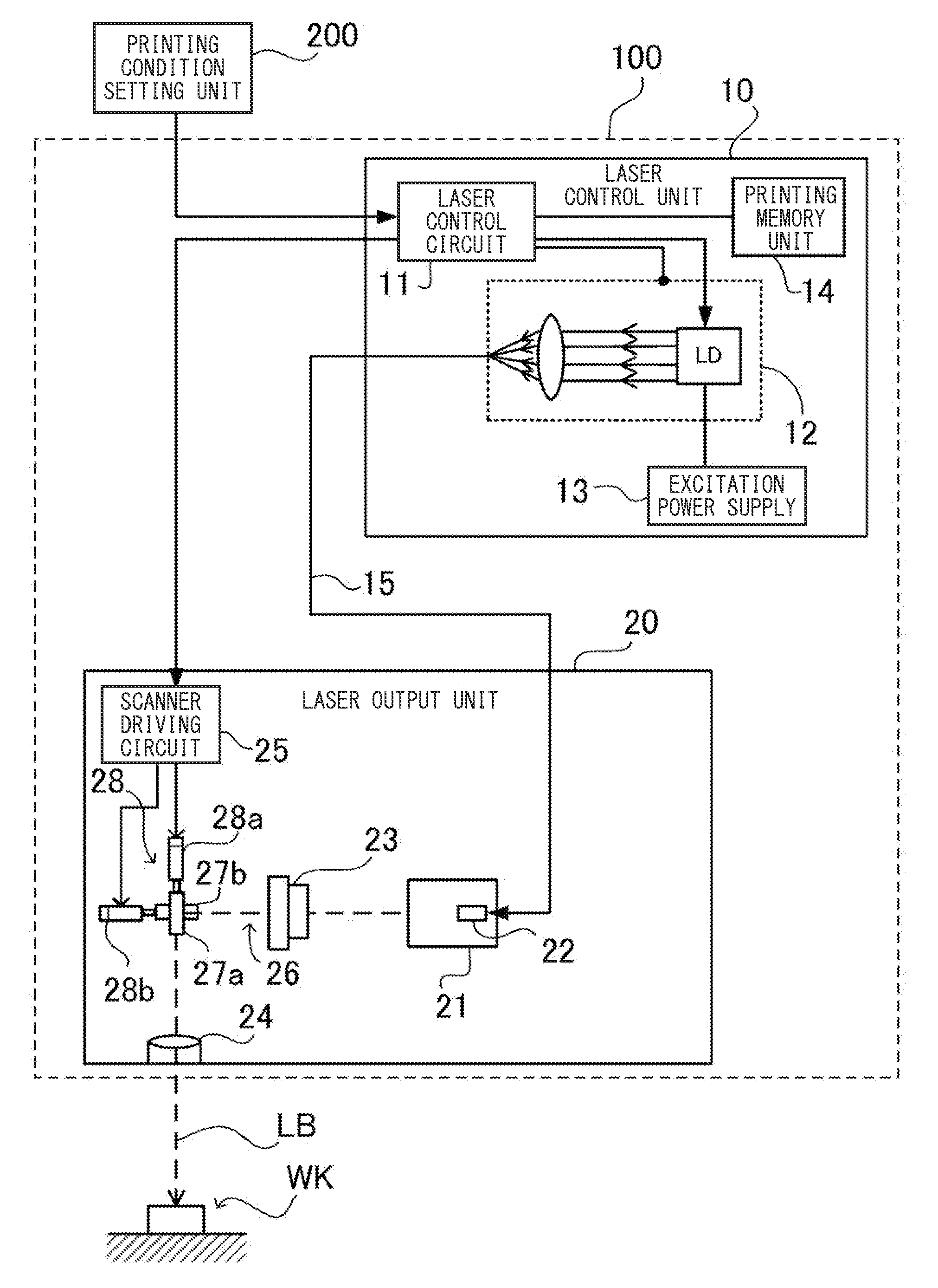
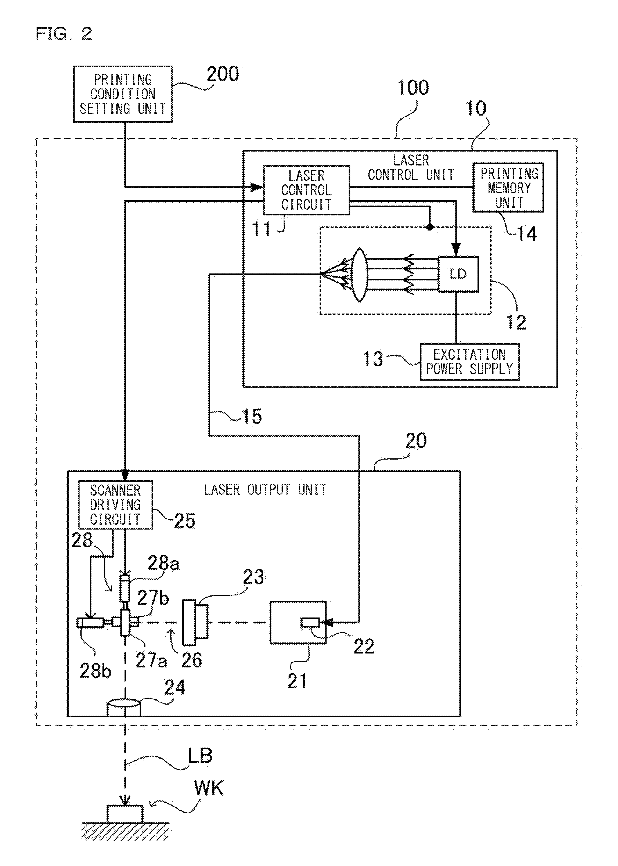
[0121]The laser marking apparatus 1000 includes a marking unit 100 that constitutes a marking section and a printing condition setting unit 200 that constitutes a printing condition setting section. As illustrated in FIG. 1, the marking unit 100 includes a laser control unit 10 and a laser output unit 20. The printing condition setting unit 200 includes a parameter setting section 32, a printing condition generating section 33, a printing data generation section 34, a printing data output section 35, a printing information code setting section 38, and an identification info...

second embodiment

[0241]A sample printing pattern in which the identification information is possessed by the specific pattern will be described as a second embodiment with reference to FIGS. 53 to 60. In the second embodiment, the sample code includes a symbol SB and the specific pattern identifying the printing position of each symbol. The specific pattern is printed near the symbol, for example, surroundings of the symbol. In FIG. 53, the symbol SB is constructed by the two-dimensional code, and a separator line DL that separates the symbols printed into the matrix shape is used as the specific pattern. That is, a separator pattern, in which the two-dimensional codes are printed into a lattice shape separated by the separator line DL, is obtained.

[0242]The printing position is identified by the specific pattern, which allows the printing condition corresponding to the printing position to be identified on the laser marking apparatus side. The symbol can also be used to identify the printing positi...

third embodiment

[0259]As described above, in the symbol and the specific pattern, which constitute the sample code, the printing quality is evaluated by the symbol and the printing position is identified by the specific pattern. In the first and second embodiments, the two-dimensional code is mainly used as the symbol by way of example. In the case that the two-dimensional code is used, the identification information such as the printing position can be encoded in the two-dimensional code. Even if the complete sample code in which some sort of information can be encoded is not used, the purpose of the printing quality evaluation can be achieved in the symbol enough to be able to evaluate the printing quality. Particularly, in the case that the symbol is formed by the complete sample code, it is necessary that the symbol has a proper size in order to encode the information. However, depending on the workpiece of the printing target, sometimes the sufficient printing size cannot be ensured. In the ca...


PUM

PropertyMeasurementUnit
sizeaaaaaaaaaa
center wavelengthaaaaaaaaaa
frequencyaaaaaaaaaa

Abstract

In order to improve read stability, a printing condition is set based on not visual read of a user, but read with an optical information reading apparatus. A printing quality evaluation apparatus includes: an image acquiring section that acquires an image; a symbol extracting section that extracts the symbol in which the printing quality can be evaluated from the captured images acquired by the image acquiring section; a printing quality evaluation section that evaluates the printing quality of the symbol extracted by the symbol extracting section; an identification information recognition section that recognizes the identification information identifying each printing condition of the symbol; and an evaluation output section that outputs the identification information, which is recognized by the identification information recognition section, and an evaluation result of the printing quality of the printing quality evaluation section according to the symbol extracted by the symbol extracting section.

Description

CROSS-REFERENCE TO RELATED APPLICATIONS[0001]The present application claims foreign priority based on Japanese Patent Application No. 2011-008797, filed Jan. 19, 2011, the contents of which is incorporated herein by reference.BACKGROUND OF THE INVENTION[0002]1. Field of the Invention[0003]The present invention relates to a laser marking apparatus that irradiates a target object with a laser beam to perform machining such as printing, a laser printing condition setting device, a printing quality evaluation system in which the laser marking apparatus and the laser printing condition setting device are combined, a laser printing condition setting method, a laser printing condition setting program, a computer-readable recording medium, an instrument in which computer-readable information is recorded, and a laser marking apparatus in which computer-readable information is recorded.[0004]2. Description of Related Art[0005]Recently, various codes such as a barcode and a two-dimensional cod...

Claims


Application Information

Patent Timeline
Patent Type & Authority Applications(United States)
IPC IPC(8): B41J2/47G06K15/02B23K26/00B41M5/26
CPCG06F3/1208G06F3/1256G06K15/12G06K5/00G06K15/027G06K1/121
Inventor MATSUDA, HAJIMEITO, TAKAAKI
Owner KEYENCE
Why Eureka
Try Eureka